


Ceiling & Floor, Ceiling Suspended (50Hz, R22) 81
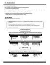
15. Installation
VB Chassis Models
15.4 Wiring Connection
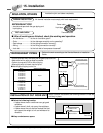
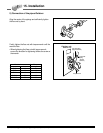
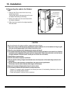
1) Connecting cables to the Indoor Unit
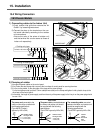
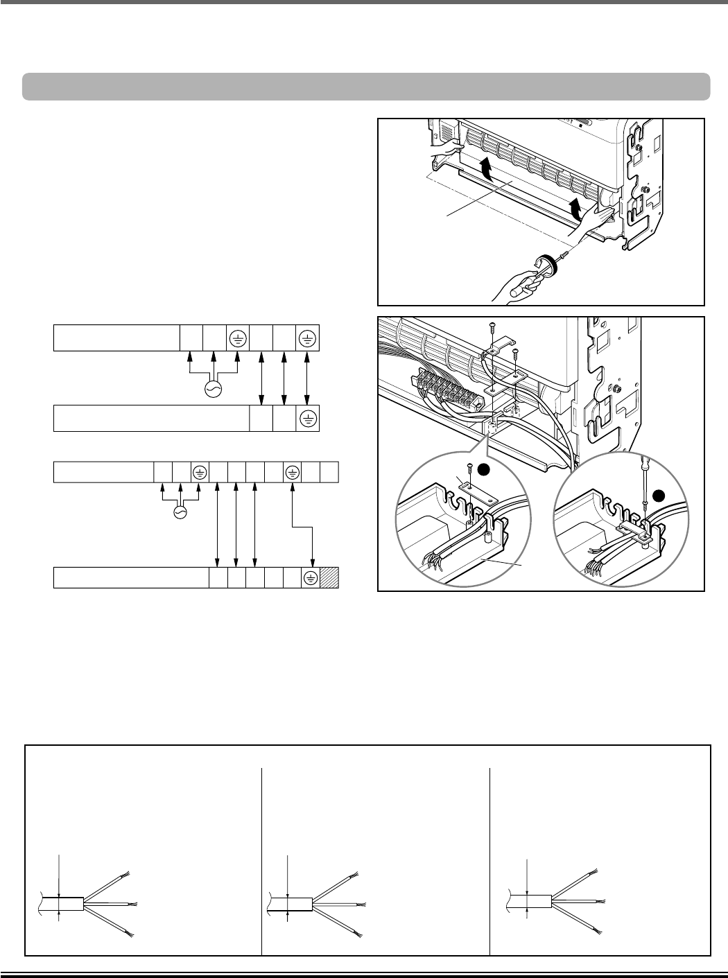
1) Firstly remove inlet grille then remove the 'Air
Guide-L' by loosening two screws.
2) Connect the wires to the terminals on the con-
trol board individually according to the outdoor
unit connections.
• Ensure the color of the wires of outdoor unit
and the terminal No. are the same as those of
indoor unit respectively
R
AIR GUIDE-L
INDOOR UNIT
Control
Panel
1
2
Clamp
Terminals on the indoor unit
POWER
INPUT
GN/YL
POWER
INPUT
GN/YL
Terminals on the indoor unit
1(L) 2(N)
34
Terminals on the outdoor unit
34
Terminals on the outdoor unit
34
567
1(L) 2(N)
3456 78
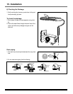
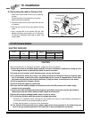
• Cooling & Heating type
• Cooling only type
NORMAL CROSS-
SECTIONAL AREA
• 2.5mm
2
(24K)
• 2.0mm
2
(18K)
NORMAL CROSS-
SECTIONAL AREA
• 2.5mm
2
(24K)
• 2.0mm
2
(18K)
NORMAL
CROSS-
SECTIONAL
AREA
0.75mm
2
The power cord connected to the
indoor unit should be complied with
the following specifications
(Type H05VV-F(Indoor)
approved by HAR or SAA).
The power cable
connected between
the indoor and outdoor unit should
be complied with the following
specifications
(Type H07RN-F approved by HAR or SAA).
The connecting cable connected
between the indoor and outdoor unit
should be complied with the
following specifications
(Type H07RN-F approved by HAR or SAA).
CAUTION
Ø8.0mm
Ø10.0mm
Ø8.0mm
Ø10.0mm
Ø6mm
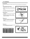
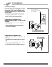
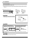
2) Clamping of cables
1) Arrange two power cables on the control panel.
2) First, fasten the steel clamp with a screw to the inner boss of control panel for securing the wires.
3) For the cooling model, fix the other side of the clamp with a screw strongly.
For the heat pump model, put the 0.75mm
2
cable(thinner cable) on the clamp and tighten it with a plastic clamp to the
other boss of the control panel.
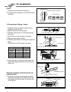
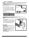
4) In Australia, the length of power supply cord from the entry of the power supply to the live pin on the power plug should
be over 1.8m.