4 Installation
The DVST Transmitter is supplied as a wall mounted unit.
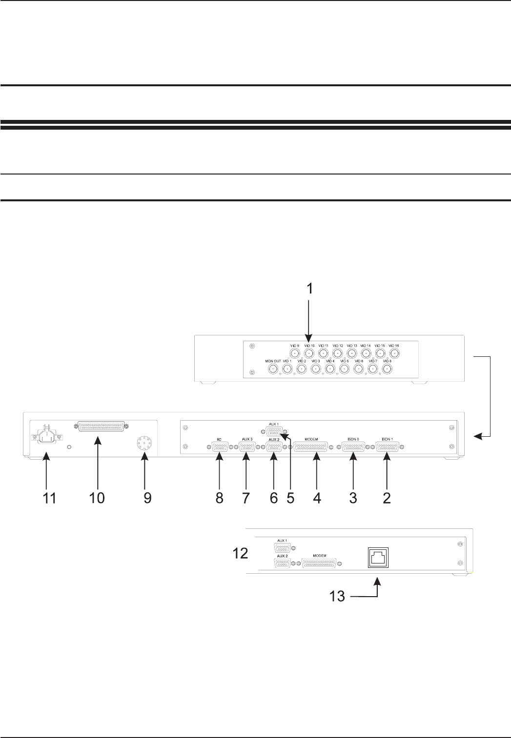
4.1 Rear Panel connections
The DVST Transciever uses BNC connectors for all video inputs and outputs. Other
data connections are made via standard D type connectors. The optional keyboard is
connected by a 9 pin D type female plug.
WARNING: DO NOT CONNECT THE UNIT TO OTHER EQUIPMENT WITH POWER ON.
Key to Fig: 1
1 Cmaera Inputs 4 Modem 7 AUX3 10 Alarm Inputs 13 ISDN
2 ISDN 1 5 AUX 1 8 IIc Socket 11 Power Connection Connection
3 ISDN 0 6 AUX 2 9 Telemetry Out 12 Integral Dataflext TA Unit
Dedicated Micros Ltd Page 7
DVST Installation Guide Installation
Fig: 1 Rear panel layout


