


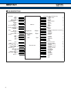
MB91401
8
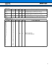
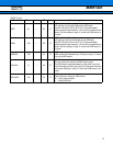
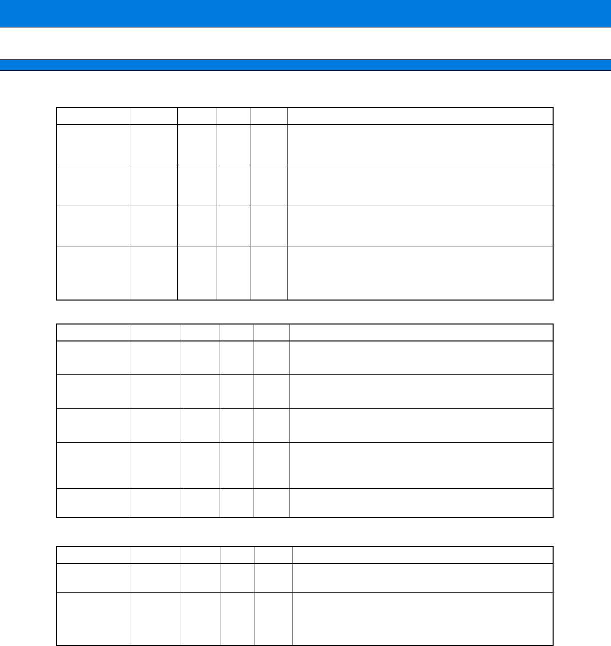
ICE (9 pin)
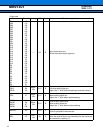
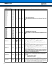
JTAG (5 pin)
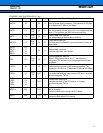
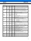
TEST (5 pin)
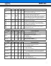
Pin name Pin no.
Polarity
I/O
Circuit
Function/application
BREAKI 76 IN D
Emulator break request pin
This pin inputs the emulator break request when an ICE is
connected.
ICS2
ICS1
ICS0
74
75
4
OUT F
Emulator chip status pins
These pins output the emulator status when an ICE is
connected.
ICLK 3 I/O B
Emulator clock pin
This pin serves as the emulator clock pin when an ICE is
connected.
ICD3
ICD2
ICD1
ICD0
140
194
139
138
I/O B
Emulator data pins
These pins serve as the emulator data bus when an ICE is
connected.
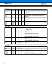
Pin name Pin no.
Polarity
I/O
Circuit
Function/application
TCK 146 IN E
JTAG test clock pin
Note : Please input “1” when unused.
TRST 78 IN E
JTAG test reset pin
Note : Please input “0” when unused.
TMS 7 IN E
TAP controller mode select pin
Note : Please input “1” when unused.
TDI 5 IN E
JTAG test data input pin
JTAG test serial data input pin.
Note : Please input “1” when unused.
TDO 141 OUT F
JTAG test data output pin
JTAG test serial data output pin
Pin name Pin no.
Polarity
I/O
Circuit
Function/application
VPD 143 IN
Mode pin
Input “0” to this pin.
TEST3
TEST2
TEST1
TEST0
84
13
82
11
IN D
Test pin
Input “0000” to this pin.
Note : Don’t set other than above description.
Prelminary
2004.11.12