


MB91401
25
•
••
•
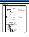
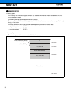
Notes as device
Treatment of Unused Input Pins
It causes the malfunction that the unused input terminal is made open, and do the processing such as 1 stack
or 0 stacks.
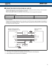
About Mode pins (MDI2 to MDI0)
Connect these pins with the input buffer by 1 to 1 to prevent the malfunction by the noise, and connect directly
to VDD or VSS outside of ASIC.
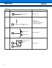
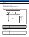
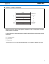
Operation at start-up
Specify set initialization reset (INIT) with the terminal INITXI when you turn on the power supply.
Moreover, connect "L" level input to the terminal INITXI until the input clock is steady.
About watch dog timer
The watchdog timer function of this macro monitors a program to check whether it delays a reset within a certain
period of time. If the program runs out of control and fails to delay the reset, the watchdog timer function resets
the CPU.
Therefore, it keeps operating until reset is specified when the watchdog timer function is made effective once.
Exceptionally, the reset postponement is automatically done under the condition that the program execution of
CPU stops. Refer to the paragraph of the function explanation of the watchdog timer for the condition of applying
to this exception.
There is a possibility that watchdog reset is not generated when entering the above-mentioned state by the
reckless driving of the system. In that case, please specify reset (INIT) from external INITX terminal.
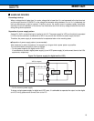
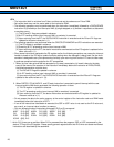
Restrictions
• Clock control block
• Secure the clock stability waiting time at "L" input to INITXI.
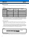
• When entering the standby mode, use the following sequences after using the synchronous standby mode
(TBCR:set at the bit8 SYNCS bit of timebase counter control register).
In addition, set the I-flag and the ILM and ICR registers to branch to an interrupt handler when the interrupt
handler triggers the microcontroller to return from the standby mode.
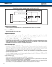
• Please do not do the following when the monitor debugger is used.
• Please do not set the break point to the above-mentioned instruction row.
(LDI #value_of_standby, R0) ; Value_of standby is write data to STCR.
(LDI #_STCR, R12) ; _STCR is address (481H) of STCR.
STB R0, @R12 ; Write to standby control register (STCR).
LDUB @R12, R0 ; STCR read for synchronous standby
LDUB @R12, R0 ; Dummy re-read of STCR
NOP
NOP
NOP
NOP
NOP
Prelminary
2004.11.12