


MB91401
22
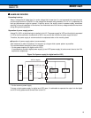
• Precaution when designing
When evaluation MCU on the user system is operated in the state that the emulator is not connected, should
be treated as follow each input terminal of evaluation MCU connected with the emulator interface on the user
system.
Therefore, note that the switch circuit etc, might become necessary in the user system when you design.
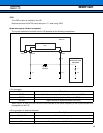
The terminal processing in each emulator interface is shown as follows.
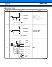
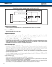
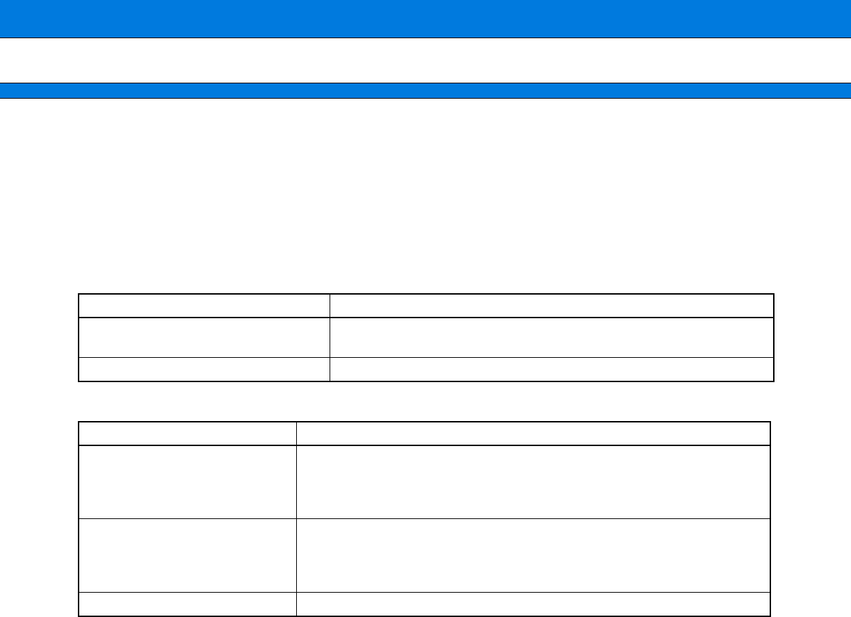
Pin treatment of emulator interface (DSU-3)
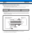
Emulator interface wiring regulations
• Reference document
Please match and refer to the following manual for the connection with ICE.
• DSU-FR Emulator MB2198-01 Hardware Manual
• FR20/30 series MB2197-01 Hardware Manual
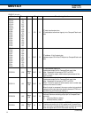
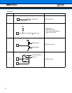
Evaluation MCU terminal name Pin treatment
RST
To be connected the RST terminal with the reset output circuit in the
user system.
Others To open.
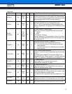
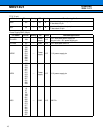
Signal line name Wiring regulations
ICLK
ICS2 to ICS0
ICD3 to ICD0
BREAKI
• The total wiring length of each signal (From evaluation MCU pin to the
emulator interface connector pin) is made within 50 mm.
• The difference of the total wiring length of each signal makes within 2 cm
and the total wiring length of ICLK is the shortest.
UV
CC
• Wire the pattern with capacity more than the ratings current.
• Each power supply and GND may cause a short-circuit or reverse connec-
tion in between by a wrong connection of a probe. Insert a protection circuit
such as a fuse into each power supply pattern to safeguard it.
GND • Connect directly with a power supply system pattern such as grandopran.
Prelminary
2004.11.12