


MB91401
12
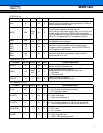
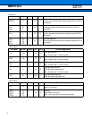
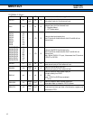
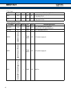
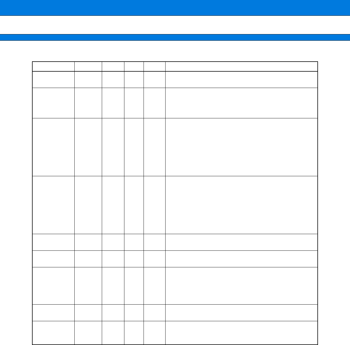
EXTERNAL IF (23 pin)
Pin name Pin no.
Polarity
I/O
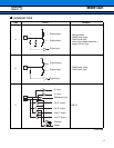
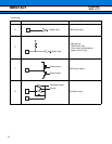
Circuit
Function/application
EXCSX 50
Nega-
tive
IN D
External chip select input pin
Chip select input pin from external host.
EXA 116 IN D
External address input pin
Address input pin from external host.
“0” : Register select
“1” : FIFO data select
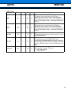
EXD15
EXD14
EXD13
EXD12
EXD11
EXD10
EXD9
EXD8
180
122
57
56
121
54
179
120
I/O B
External data input/output pins
The I/O terminal of data bus bit of bit15 to bit8 with an
external host.
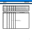
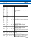
EXD7/GPIO7
EXD6/GPIO6
EXD5/GPIO5
EXD4/GPIO4
EXD3/GPIO3
EXD2/GPIO2
EXD1/GPIO1
EXD0/GPIO0
53
178
119
52
228
177
118
51
I/O B
External data/GPIO input/output pins
The I/O terminal of data bus bit of bit7 to bit0 with an
external host.
Note : When EXIS16 “0” input, it becomes the I/O terminal
of GPIO7 to GPIO0.
EXRDX 117
Nega-
tive
IN D
External read strobing input pin
Read strove input pin from external host
EXWRX 176
Nega-
tive
IN D
External write strobing input pin
Write strove input pin from external host
EXIS16 49 IN D
External data bus width select input pin
Bit width select pin of EXD
“0” : 8 bit
(Note : EXD15 to EXD8 are enabled.)
“1” : 16 bit
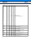
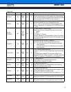
DREQRX 174
Nega-
tive
OUT F
External reception data request output pin
Recordable data to reception FIFO is shown.
DREQTX 175
Nega-
tive
OUT F
External transfer data request output pin
It is shown that there are data in transmission register and
transmission FIFO.
Prelminary
2004.11.12