MB91401
32
■
■■
■
MODE SETTINGS
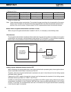
The FR family uses the mode pins (MDI2 to MDI0) and the mode register (MODR) to set the operation mode.
•
••
•
Mode Pins
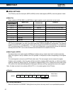
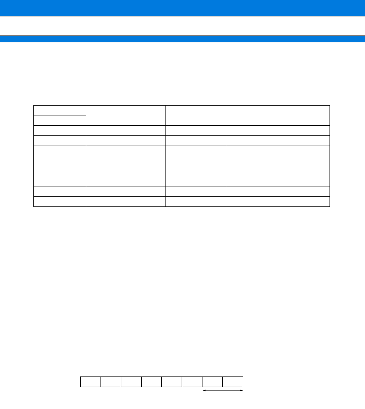
Three mode pins MDI[2], MDI[1], and MDI[0] are used to specify a mode vector fetch or test mode.
Setting MDI2 to MDI0 to "010", USRTEST is set to "1" and the device operates in the user circuit test mode. The
FR71 core is suspended in the user circuit test mode while SYSCLK and MCLKO are operating. The reserved
modes include the FR71 core test mode. In this case, the signal at the FRTEST pin becomes "1" and enters the
FR71 core test mode. If the FRTEST pin = "1", that circuit configuration is required which allows the separately
defined pins of the FR71 core to be controlled and monitored from the outside of the chip.
•
••
•
Mode Register (MODR)
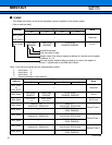
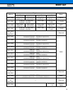
The data written to the mode register (MODR) by hardware using a mode vector fetch is called mode data.
When this register is set by hardware, the CPU operates in the operation mode corresponding to the register
setting.
The mode register is set only by an INIT-level reset cause. The user program cannot access this register.
However, as an exception, when the macro shifts to emulation mode by INTE instruction, or shifts to emulation
mode by a break at a debug using ICE, this register is mapped at 0000_07FD
H. Select this function when using
ICE, perform the mode data setting before the program loading by writing a appropriate value to this register.
Note : No data is existed in the address (0000_07FFH ) in the mode register of the FR family.
•
••
•
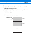
Register
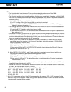
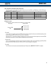
[bit7 to bit2] Reserved bit
Be sure to set this bit to “000000”. Setting them to any other value may result in an unpredictable operation.
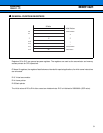
Mode pins
Mode name
Reset vector
access area
Remarks
MDI2 to MDI0
0 0 0 Reserved
0 0 1 external ROM mode vector External Bus width is set by the mode data.
0 1 0 User circuit test FR stops (with clock signal supplied).
0 1 1 Reserved
1 0 0 Reserved
1 0 1 Reserved
1 1 0 Reserved
1 1 1 Reserved
Initial Value
MODR XXXXXXXX
B
76543210
0 0 0 0 0 0 WTH1 WTH0
Operation mode setting bits
Prelminary
2004.11.12


