MB91401
14
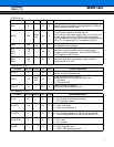
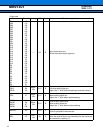
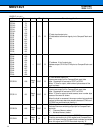
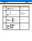
CARD IF (41 pin)
(Continued)
Pin name Pin no.
Polarity
I/O
Circuit
Function/application
CFD15
CFD14
CFD13
CFD12
CFD11
CFD10
CFD9
CFD8
CFD7
CFD6
CFD5
CFD4
CFD3
CFD2
CFD0
CFD0
2
73
72
137
136
71
192
135
70
240
191
134
69
190
133
68
I/O B
CF data input/output pins
I/O data/status/command signal pin to CompactFlash card
side
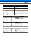
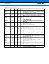
CFA10
CFA9
CFA8
CFA7
CFA6
CFA5
CFA4
CFA3
CFA2
CFA1
CFA0
189
132
67
188
131
66
236
187
130
65
186
OUT B
CF address 10 to 0 output pins
Address output CFA10 to CFA0 pins to CompactFlash card
side
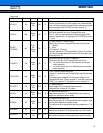
CFCE2X 128
Nega-
tive
OUT B
CF card enable output pin
Byte access output pin to CompactFlash card side
Note : Supported for access to CFD7 to CFD0.
When “L” level is output, odd number byte access of the
word is shown.
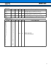
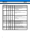
CFCE1X 63
Nega-
tive
OUT B
CF card enable output pin
Byte access output pin to CompactFlash card side
Note : Supported for access to CFD7 to CFD0.
When “L” level is output at word access, even number byte
access of the word is shown.
When the byte is accessed, the even number byte and odd
number byte access become possible because CFA0 and
CFCE2X are combined and used by it.
CFREGX 185
Nega-
tive
OUT B
CF Attribute/Common switching output pin
Attribute/Common switching output pin to CompactFlash
card side
“H” : Common Memory select
“L” : Attribute Memory select
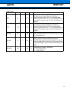
CFCD2X 123
Nega-
tive
IN E
Card connection detect input pin : CFCD2X
Checking connection pin of the socket and CompactFlash
card. It is shown that the CompactFlash card was connected
when this signal and CFCD1X are both input by “0”.
Prelminary
2004.11.12


