


27
Initial Installation
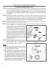
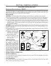
AUTOMATIC SAFETY SHUT DOWN:
If the spill switch is activated and shuts off the main burner the following procedure should be
followed.
• Is the pilot ame still on? If not, the reason for the replace shut down is not the spill
switch.
• Turn off the pilot ame and turn off all controls. Let replace to cool down. Refer to Owner’s Manual.
• Check for blockages or restrictions in the ue and venting components.
• Restart the replace and check for vent draft as described earlier.
• Operate the replace in a normal manner.
• If the main burner shuts down again after a period of operation, turn off the replace and contact your
service technician.
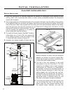
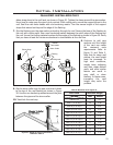
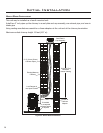
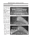
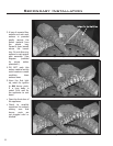
SPILL SWITCH REPLACEMENT:
Use the following instructions to replace the
Safety Spill Switch.
1. Turn the unit off and allow it to cool.
2. Disconnect the spill switch wires from the
valve and on/off/remote rocker switch wire
(see Figure 39).
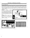
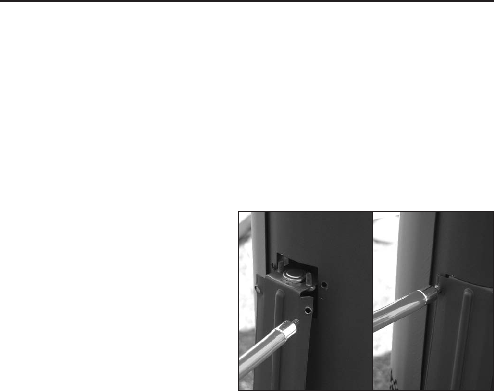
3. Remove the four mounting screws holding the
spill switch bracket and remove the bracket
(see Figure 43).
4. Remove and replace the spill switch with a
50-885 Spill Switch Assembly using a T-20
torx type driver.
5. Follow the reverse of the previous steps.
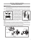
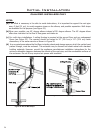
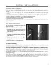
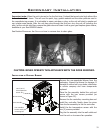
OPTIONAL FINISHING:
In installations where the ue connector is running from the drafthood into a non-combustible chimney
the following optional nishing technique can be used.
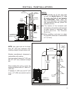
CAUTION: Installations where the ue connector or venting connects to, or passes through,
combustible walls or ceilings, the inner vent components must be ‘B-vent’. It is not allowable
in these applications to use single wall inner vent components.
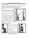
For decorative purposes a 6” (15 cm) single wall black stove pipe may be installed over the 4” (10 cm)
single wall or ‘B-Vent’.
Note: The use of these components is for aesthetic purposes only and does not effect the
fact that the replace, when tted with the Drafthood Adaptor, is a Natural Vent appliance
and therefore draws air in through the Drafthood Adaptor intake ports.
Figure 43: Spill switch installation.