


11
Maintenance And Service
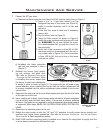
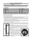
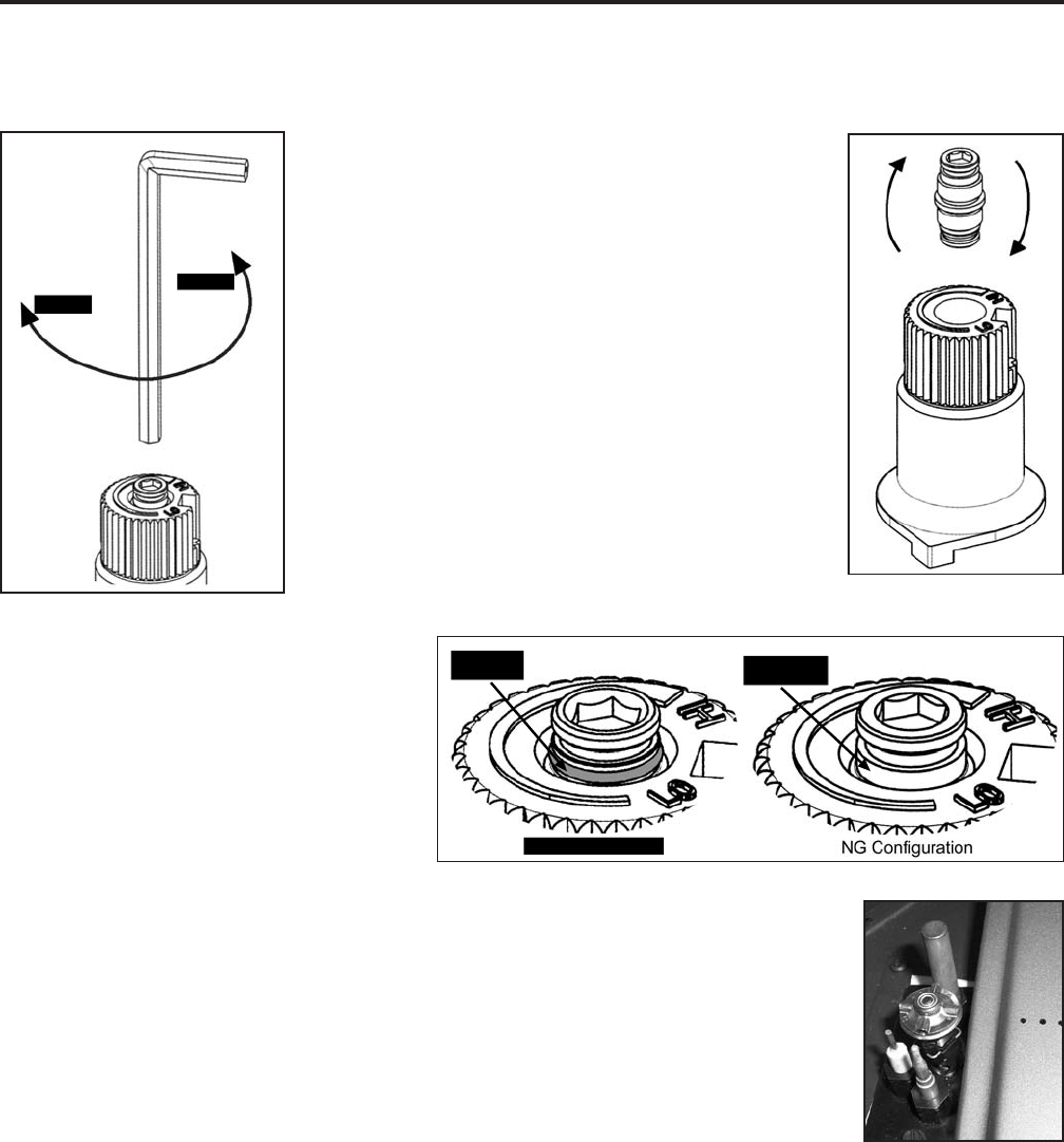
b) Insert a
5
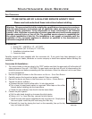
/32” or 4 mm Allen wrench into the
hexagonal key-way of the screw (see Figure 8),
rotate it counter-clockwise until it is free and
extract it.
c) Check that the screw is clean and if necessary
remove dirt.
d) Flip the screw (refer to Figure 9).
e) Using the Allen wrench as shown in Figure 8,
rotate the screw clockwise until a torque of 9 inch
lbs. WARNING! Do not over tighten the screw.
It is recommended that you grip the wrench by
the short side.
f) Verify that if the conversion is from NG to LPG,
the screw must be re-assembled with the red o-
ring visible (refer to Figure 10). If the conversion
is from LPG to NG, the red o-ring of the screw
must be not visible.
Figure 9: Flip valve
screw.
Red o-ring
is not visible
Red o-ring
is visible
LPG Configuration
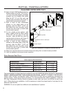
g) Re-attach the black protection
cap that was removed in step a
(Figure 7).
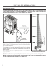
8. Reinstall the burner, brick panels,
log set, embers, and glass door.
Also refer to SECONDARY INSTALLATION
- INSTALLING LOG SET AND EMBERS. When
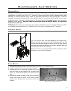
re-installing the burner, ensure that
the burner to pilot hood relationship
Figure 10: O-ring on valve screw.
is similar to what is shown in Figure 11. On some units you will need to pay
special attention when installing the burner that the venturi adjustment rod
is properly installed into the venturi adjustment piece welded to the burner
venturi tube
9. Reconnect the main gas line if it was disconnected and open the shut-off valve
at the gas line to the unit.
10. Use a small brush to apply a warm soapy water solution to all gas connections
(use a half dish soap and half warm water). If a gas leak is present, bubbling
will occur. Gas leaks can be repaired by using an approved pipe thread sealant
or approved Teon tape. NEVER USE AN OPEN FLAME WHEN TESTING FOR
LEAKS.
Loosen
Tighten
Figure 8: Removing valve screw.
7. Convert the SIT gas valve:
a) Remove the black protection cap from the HI/LO knob by hand shown in Figure 7.
Figure 11. Ignitor
assembly beside the
burner.
11. Reconnect the electrical power to the unit.
12. Relight the main burner in both the “HI” and “LO” positions to verify proper burner ignition and
operation and proper ame appearance. Also refer to SECONDARY INSTALLATION - LOG SET AND EMBERS
INSTALLATION for a ame appearance picture.
13. MAKE SURE that the conversion label is installed on or close to the rating label to signify that the
unit has been converted to a different fuel type.