


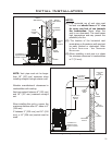
elbows necessary to reach from the appliance
adapter up through the Round Support Box.
Insure that all pipe and elbow connections are
in their fully twist-locked position.
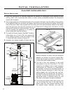
5. Cut hole in the roof centered on the small
hole placed in the roof from Step 2. The hole
should be of sufcient size to meet minimum
requirements for Clearance to Combustibles,
as specied. Continue to assemble lengths of
pipe and elbows necessary to reach from the
ceiling support box up through the roof line.
Galvanized pipe and elbows may be utilized in
the attic, as well as above the roof line. The
galvanized nish is desirable above the roof
line, due to the higher corrosion resistance.
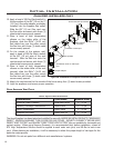
6. Once the pipe sections have been joined, and
run up through the hole in the roof, slip an
elbow strap over the exposed sections, bend
the support straps outwards, and push the
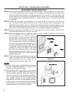
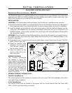
Initial Installation
QUALIFIED INSTALLERS ONLY
VERTICAL INSTALLATION:
1. Check the instructions for required clearances (air spaces) to combustibles when passing through
ceilings, walls, roofs, enclosures, attic rafters, or other nearby combustible surfaces. Do not pack air
spaces with insulation.
2. Set the gas appliance in the desired location. Drop a plumb bob down from the ceiling to the position
of the appliance ue exit, and mark the location where the vent will penetrate the ceiling. Drill a small
hole at this point. Next, drop a plumb bob from the roof to the hole previously drilled in the ceiling,
mark the spot where the vent will penetrate the roof. Determine if ceiling joists, roof rafters, or other
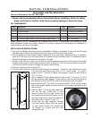
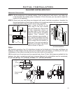
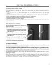
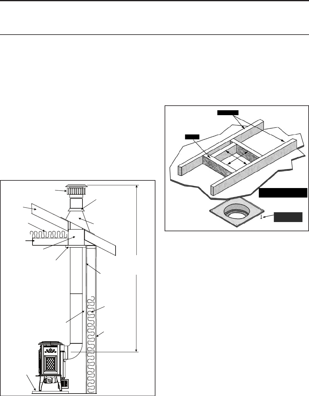
1
1
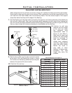
/
2
” (4cm) long
wood screw (x4)
10” (25.4cm) x10” (25.4cm)
inside framing
Ceiling Joist
Framing
Figure 28: Wall Framing Hole for Vertical Installation.
framing will obstruct the venting system. You may
wish to relocate the appliance, or to offset, to
avoid cutting load bearing members.
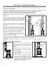
3. To install the Round Support Box/Wall Thimble in
a at ceiling, cut a 10 inch (25.4 cm) square hole
in the ceiling, centered in the hole drilled in Step
2. Frame the hole as shown in Figure 29.
4. Assemble the desired lengths of black pipe and
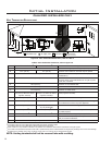
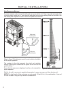
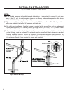
Vertical
Vent Cap
Roof
Truss
Insulation
Insulation
Guard
Ceiling
Rafter
Support
Collar
Storm
Collar
Roof Flashing
15 feet (4.57m)
Maximum
Vertical
Venting
Interior Wall
Surface
Insulation
Minimum
Clearance to
Combustibles
Exterior
Wall Surface
If installed
on a carpeted
surfacea hearth
is required
Figure 29: Vertical Installation.
22