


15
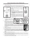
Initial Installation
QUALIFIED INSTALLERS ONLY
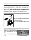
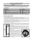
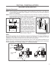
Figure 16: Wire Spacers.
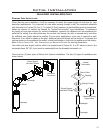
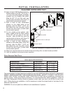
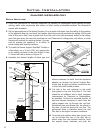
it to the inner wall frame using four (4) 1” wood screws. If a wall is
greater than 8” (203mm) in depth, the clearance above the ex must be
4” (111mm)
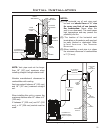
6. Apply a bead of Mill-Pac Black sealant to the new Ø4” (10 cm) by 5” (12.5
cm) provided ue collar adaptor. Press the ue collar into the ue outlet of
the replace so that the Mill-Pac seals the ue collar to the ue outlet.
7. Stretch both the Ø4” (10 cm) ex vent and the Ø6” (16.25 cm) ex intake
liner to the length needed to ensure the ex can be easily connected to the
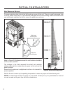
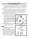
Figure 17: Wire Spacer in Place.
vent terminal.
8. Slide the Ø6” (16.25 cm) ex intake liner
over the ex vent. Install four (4) wire
spacers around the ex pipe. Ensure the
wire spacers are positioned at either end of
the pipes, and at each end of any elbows in
the liners (refer to Figure 16 and 17).
9. Install the ex pipe assembly through
the wall thimble, ensure that this portion
of pipe slides through the outside wall
far enough to connect onto the vent
termination cap.
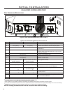
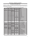
KIT COMPONENTS:
Qnty Description Qnty Description
1 Horizontal direct vent termination cap 4 Wire spacers
1 Flue collar adapter 1 4 oz tube Mill-Pac Sealant
1 Wall thimble 1 4 oz tube RTV silicone
1 5’ (190 cm) length of Ø4” (10 cm) double walled ex pipe 12
9
/16” tech screws
1 5’ (190 cm) length of Ø6” (16.8 cm) double walled ex pipe 8 1” wood screws
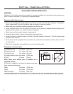
Please ensure that all components are supplied with this kit. If components are missing or have
been damaged, contact your dealer, distributor, or courier company. Do not attempt the installation if
components are missing or damaged.
INSTALLATION INSTRUCTIONS:
1. Plan your installation and clearances to combustibles. Decide on a location for the unit that will meet
the clearances noted in the venting section, and any or all local code requirements.
2. Set the appliance in the desired location. Determine if any wall studs, electrical wiring, or plumbing
pipes are in the way of the venting system as it passes through the exterior wall. The replace location
should be adjusted if obstructions are found in the wall.
3. Project a line from the center point of the ue outlet upward and outward to the desired ue outlet
location on the exterior wall. Using this center point, scribe a 10” (25.4 cm) hole or square on the wall.
Cut the hole from the interior through the exterior wall surfaces.
4. Frame the hole as shown in Figure 22.
5. Trim the wall thimble to match the wall thickness as necessary. Install the wall thimble and secure
Please read and understand these instructions before installing. Failure to follow
these instructions carefully could cause property damage or personal injury.
FIREPLACE HORIZONTAL VENT KIT 50-1235: