


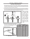
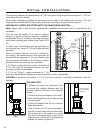
the cap assembly. It is important that the
vent pipe extend into the vent cap a sufcient
distance with a minimum of 1” (3.2 cm)
overlap. Secure the connection between the
vent cap pipe and the vent cap by attaching
the two sheet metal straps extending from
the vent cap assembly into the outer wall of
the vent pipe. Use the two sheet metal screws
provided to connect the straps to the vent
pipe. Bend any remaining portion of the sheet
metal straps back towards the vent cap, so the
decorative wall thimble will conceal it (see left
image in Figure 23).
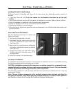
STEP 7. Slide the decorative wall thimble up to the wall
surface and attach with the screws provided.
Apply decorative brass or chrome trim if
desired (see right image in Figure 23).
NOTES:
(1) The four wood screws provided should be replaced
with the appropriate fasteners for stucco, brick,
concrete, or other types of siding.
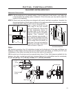
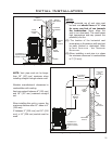
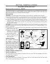
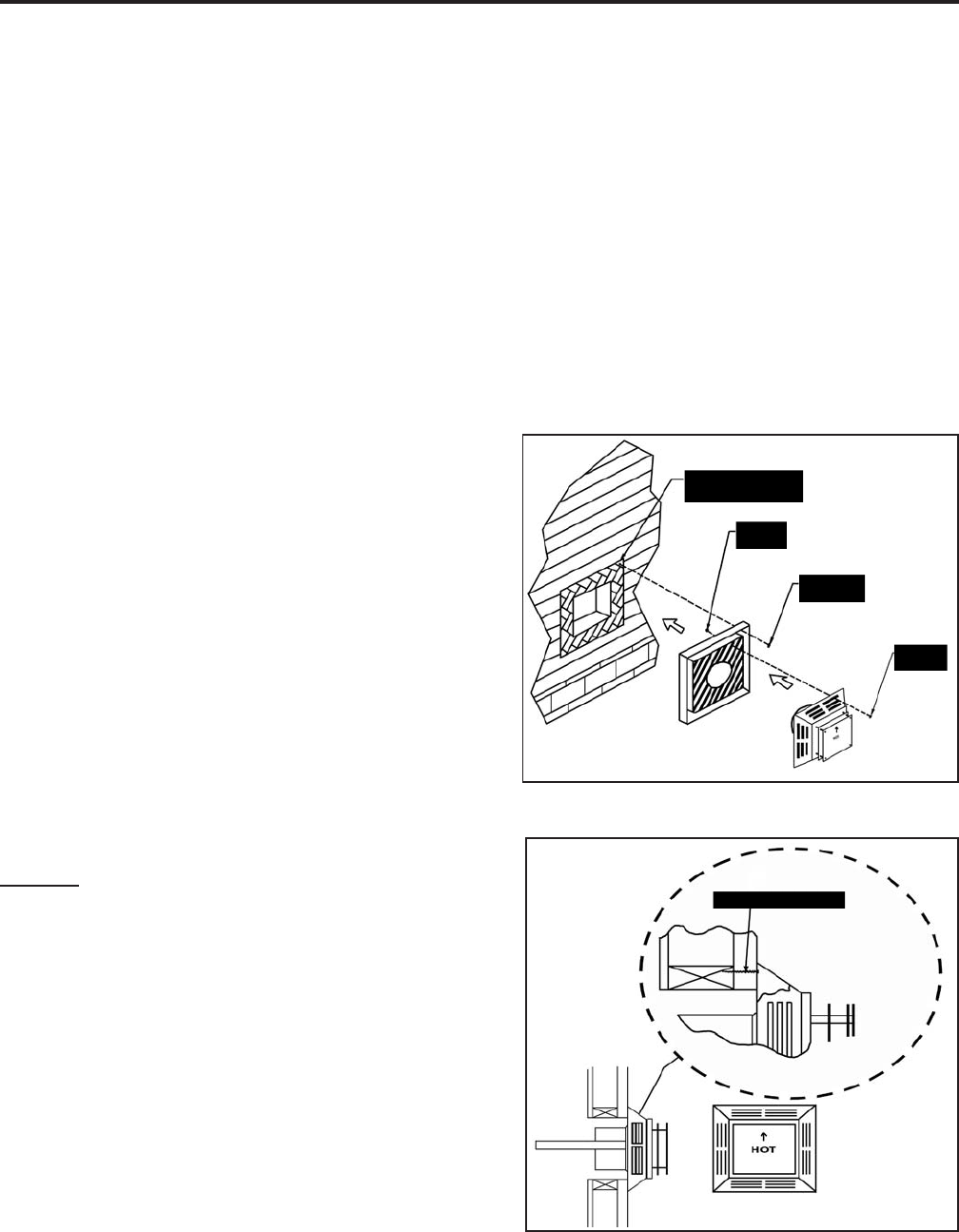
(2) For buildings with vinyl siding, a vinyl siding
standoff, should be installed between the vent cap
and the exterior wall (see Figure 24). Attach the
vinyl siding standoff to the horizontal termination.
The vinyl siding standoff prevents excessive heat
from possibly melting the vinyl siding material.
Note that the horizontal vent termination bolts onto
the at portion of the vinyl siding standoff (shaded
area in Figure 24), so that an air space will exist
between the wall and the vent termination.
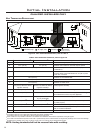
Initial Installation
QUALIFIED INSTALLERS ONLY
Wood screws (x4)
Cut vinyl siding
away to fit standoff
Bolt (x4)
required
Nut (x4)
required
Wood
screw (x4)
Figure 24: Installing Vent Cap with Vinyl Siding
Stand-Off.
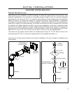
Figure 25: Installing Horizontal Vent Termination.
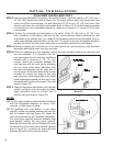
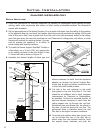
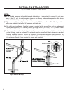
STEP 3. With the pipe attached to the stove in the correct location, mark the wall for a 10” (25.4 cm) x
10” (25.4 cm) square hole (refer to Figure 22). The center of the square hole should match the
center line of the horizontal pipe. Cut and frame the 10” (25.4 cm) x 10” (25.4 cm) hole in the
exterior wall where the vent will be terminated. Refer to Figure 15. If the wall being penetrated
is constructed of non-combustible material i.e. masonry or concrete, a 7 inches (17.8 cm) hole
is acceptable.
STEP 4. Position the horizontal vent termination in the center of the 10” (25.4 cm) x 10” (25.4 cm)
hole, and attach to the exterior wall with the four screws provided. Before attaching the vent
termination to the exterior wall, run a bead of non-hardening mastic around the edges, so as to
make a seal between the termination and the wall. The arrow on the vent termination should be
pointing up, insure that the proper clearances to combustible materials are maintained.
STEP 5. Before connecting the horizontal run of the vent pipe to the vent termination, slide the black
decorative wall thimble cover over the vent pipe.
STEP 6. Slide the appliance and vent assembly towards the wall, carefully inserting the vent pipe into
20