


7
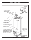
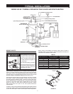
TYPICAL INSTALLATION
* CAUTION HARNESS HAS 120 VAC. IN OPERATION.
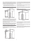
** See “PLANNING THE VENT SYSTEM”, “CONDENSATE” and “BLOWER ASSEMBLY INSTALLATION” for more
information.
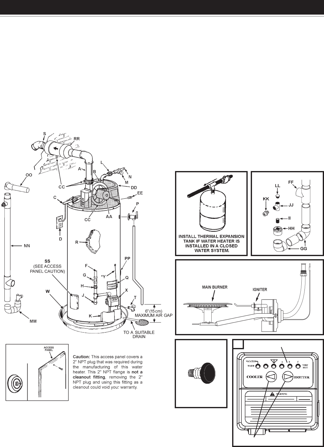
*** The side recirculation loop connections may not be used as the primary water inlet and outlet connections.
For your convenience, plugs are installed in these ttings at the factory. Remove these plugs if needed for
your specic installation. Otherwise (as with all connections) check for leaks while lling the tank with water
and after completing the installation.
FIGURE 1
VACUUM RELIEF
VALVE
*INSTALL PER
LOCAL CODES
TEMPERATURE ADJUSTMENT BUTTONS
TEMPERATURE INDICATORS
(X)
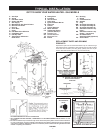
Q Rating Plate
R Insulation
S Vent Terminal
T Drain Valve
U Igniter And Main Burner
W Drain Pan
X Control
Y Control Harness*
AA Motor & Blower
CC Condensate Fitting
(4 Places Shown)**
DD Plastic Top
EE On/Off Switch
FF Exhaust Tee
GG Elbow
GET TO KNOW YOUR WATER HEATER - GAS MODELS
A Vent Pipe
B Anode
C Hot Water Outlet
D Outlet (120 VAC)
F Gas Supply
G Main Manual Gas Shut Off Valve
H Ground Joint Union
J Dirt Leg
K Outer Door
L Union
M Inlet Water Shut Off Valve
N Cold Water Inlet
O Inlet Dip Tube
P Temperature & Pressure
Relief Valve
H H Bushing
II Nipple
JJ Condensate Tee
KK Adapter
LL Plug
MM Vent Pipe Assembly #1
NN Vent Pipe Assembly #2
OO Vent Pipe Assembly #3
PP Side Recirculation Loop
Inlet***
QQ Side Recirculation Loop
Outlet*** (not shown)
RR Vent Attenuation
Assembly (VAA) (Optional)
SS Access Door
CONDENSATE ASSEMBLY
(U) NATURAL GAS MAIN BURNER
WITH IGNITER ASSEMBLY
SIDE VIEW
REPLACEMENT PARTS AND DELIMING
PRODUCTS
Replacement parts and recommended delimer may be ordered through
authorized servicers or distributors. When ordering parts, provide complete
model and serial numbers (see rating plate), quantity and name of part
desired. Standard hardware items may be purchased locally.