


21
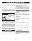
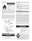
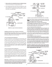
ThecondensatetrapmaybeprimedbyllingtheCONDENSATE
U-ASSEMBLY with tap water while the water heater is not operating.
The system is fully primed when the water level reaches the adaptor
connected into the Tee. In most installations the water heater will self-
primethecondensatetrapduringtherstfullheat-upcycle.Ifasound
of air bubbling through water (gurgling) is heard while the blower is
operatingaftertherstheat-upcycle,thenturntheunitoffandcontact
your plumber or service representative.
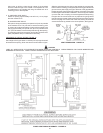
If these instructions are not followed, the condensate build-up
will block the exhaust outlet, which will cause improper operation.
Do NOT
block or
plug any
hole in this
hex plug.
DRAIN LINE
CONDENSATE
U-ASSEMBLY,
AKA. VENT PIPE
ASSEMBLY #1
*NO PORTION OF THE FIELD SUPPLIED DRAIN LINE BEYOND
THE 1/2" ADAPTOR MAY BE ELEVATED HIGHER THAN THE
ADAPTOR. THIS MUST BE TRUE FOR THE ENTIRE LENGTH
OF DRAIN LINE INCLUDING EXIT INTO AN APPROPRIATE DRAIN.
APPROXIMATELY
0.25" (0.64 cm)
FIGURE 16.
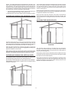
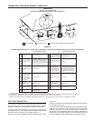
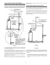
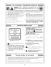
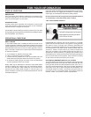
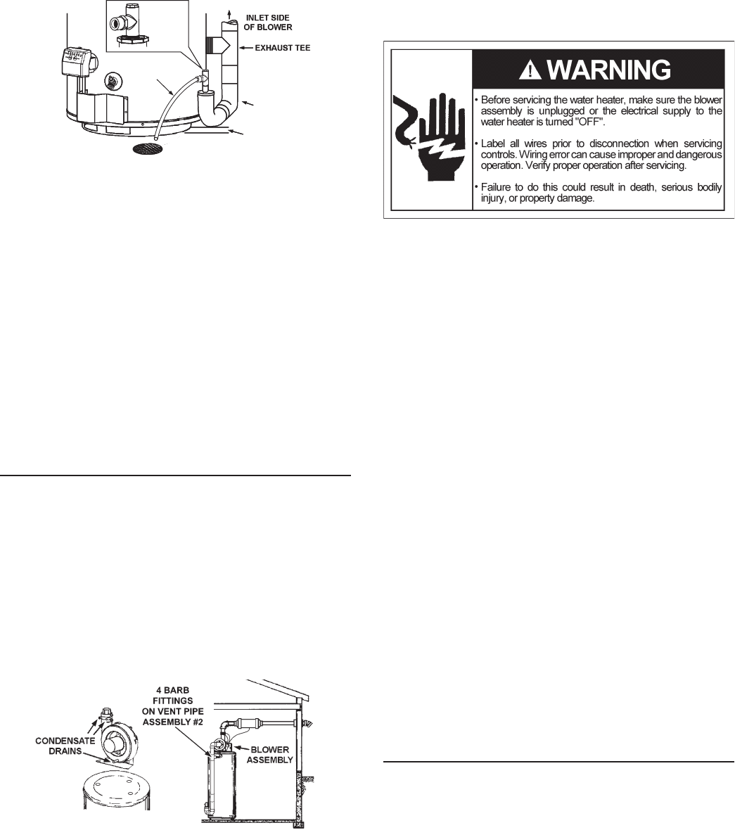
Condensate is likely to form in the venting system attached to
this water heater. The vent pipe should be sloped downward
away from the blower assembly (not less than 1/8” (3.2 mm)
nor greater than 1/2” (12.7 mm) per foot (30 cm) maximum). If
the vent piping is vented level or sloped upwards away from the
blower assembly, then adequate means for draining and disposing
of the condensate needs to be made by the installer. Two 3/8”
condensate hoses should be connected to the built in drain ports
of blower outlet adaptor. If a VAA is installed, a 3/8” condensate
hose should be connected to the barb fitting on it; otherwise the
unused barb fitting on vent pipe assembly #2 should be plugged
with one of the break-away plugs. See Figure 17.
Condensate neutralizer kits are available. Contact your distributor
or Service Agency.
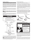
BLOWER ASSEMBLY INSTALLATION
1. This power vented water heater comes with blower assembly
installed.
2. After unit is set in place, make sure blower assembly is still mounted
securely. Also make sure both drain ports of rubber boot vent adapter
are capped off. Lastly, make sure there is no damage to blower.
3. Condensate drains from three locations on blower assembly. See
Figure17.Oneexiblehoserunsfrombottomofblowerhousing;
two run from the ports of rubber connector at the outlet of blower.
Allthesethreecondensatehosesareconnectedtobarbttingsat
vent pipe assembly #2. The hose from bottom of blower housing is
clamped by two clamps and the two hoses from rubber connector
are harnessed by another clamp. Make sure there is no kink or twist.
FIGURE 17.
4. Make sure there is no packing material in the inlet or discharge
of the blower.
5. Make sure that the plastic tubing is still attached from the air
pressure switch to the port on the blower housing. Make sure
the plastic tubing is not folded anywhere between the pressure
switch and the blower housing.
6. Make sure the ON/OFF switch is in the OFF position and that
the outer harness is connected from the blower control box to
the connector on the bottom side of the gas valve.
7. If the outer harness is not factory installed, make sure the ON/
OFF switch is in the OFF position and then connect the outer
harness from the blower control box to the connector on the
bottom side of the gas valve.
8. Do not plug in power cord until vent system is completely
installed. The Power Vent operates on 110-120 Vac. therefore
a grounded outlet must be within reach of the 6 foot (1.8 m)
exiblepowercordsuppliedwiththevent(SeeFigure1).The
power cord supplied may be used on a unit only where local
codespermit.Iflocalcodesdonotpermituseofexiblepower
supply cord:
A. Make sure the unit is unplugged from the wall outlet. Remove
the plastic top cap. Remove screws and open panel on the
front of the control box on the blower.
B. Cuttheexiblepowercord,leavingenoughtobeableto
makeconnections.Removethestrainreliefttingfromthe
box.
C. Installasuitableconduitttinginsidetheenclosure.
D. Spliceeldwiringintoexistingwiringusingcodeauthorized
method (wire nuts, etc).
E. Be certain that neutral and line connections are not reversed
when making these connections (proper polarity).
F. Ground heater properly. This water heater must be grounded
in accordance with the Canadian Electrical Code C22.1 and/
or local codes. These must be followed in all cases.
The water heater must be connected to a grounded metal,
permanent wiring system; or an equipment grounding
conductor must be run with the circuit conductors and
connected to the equipment grounding terminal or lead on
the water heater, see Figure 19.
G. Close the panel on the control box. Make sure that the access
panel is secured shut.
9. The blower discharge boot is made to accept only straight
sections of 2” pipe. To start off with an elbow, a short section
of the furnished pipe, a minimum of 2 inches (5.1 cm), must be
cut and glued into the end of the elbow that will mount on the
discharge boot.
VENT TERMINAL INSTALLATION, SIDEWALL
1. Install the vent terminal by using the cover plate as a template to
mark the hole for the vent pipe to pass through the wall. BEWARE
OF CONCEALED WIRING AND PIPING INSIDE THE WALL.
2. IftheVentTerminalisbeinginstalledonoutsideofanished
wall, it may be easier to mark both the inside and outside wall.