


23
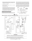
INSTALLATION OF VENT SYSTEM, SIDEWALL
With the route of the venting system and selection of materials completed,
as discussed in the section of this manual titled PLANNING THE VENT
SYSTEM,thethroughthewallventterminalinplaceandtherstsection
ofpiping,uptorstelbow,installedatthebloweritistimetocomplete
the installation of the venting system for the sidewall installation.
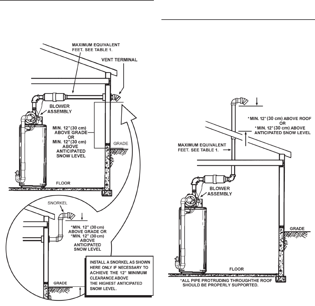
FIGURE 20
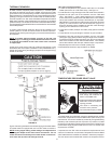
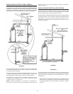
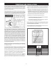
It is recommended that the completion of the venting system start
at the blower assembly and run to the coupling on the inside wall
of the vent terminal, Figure18.
The vent system piping should be supported every 5 feet (1.5 m)
of vertical run and every 3 feet (91 cm) of horizontal run. Follow vent
pipemanufacturer’sinstructionsforproperjoiningprocedures.
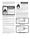
If necessary to achieve the 12” minimum clearance above
the highest anticipated snow level, install a snorkel as shown
in bottom portion of Figure 20.
NOTE: With the installation of a snorkel it is necessary to
usetwo90°elbowsthatshallbeconsideredalongwiththe
additional vent pipe when calculating maximum equivalent
feet of venting.
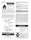
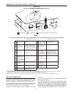
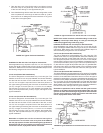
INSTALLATION OF VERTICAL VENT SYSTEM
A proper flashing or “BOOT” should be used to seal the pipe
where it exits the roof. The total vent system should not exceed
the equivalent feet of pipe as listed in Table 1.
Provide support for all pipe protruding through the roof. All piping should
be properly secured. The vent system piping should be supported
every 5 feet (1.5 m) of vertical run and every 3 feet (91 cm) of
horizontalrun.Followventpipemanufacturer’sinstructionsforproper
joining procedures.
FIGURE 21
IMPORTANT
The vent system must terminate so that proper clearances are
maintained as cited in local codes or the current edition of the Natural
Gas and Propane Installation Code (CAN/CSA-B149.1) and as
listed below:
1. Vent Termination must extend a minimum of 12 inches (30 cm)
above roof or 12 inches (30 cm) above the anticipated snow level
to prevent blockage of the vent termination, as shown in Figures
20 and 21.