


18
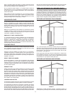
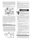
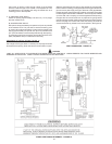
SEDIMENT TRAPS
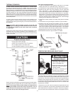
A sediment trap should be installed as close to the inlet of the water
heater as practical at the time of water heater installation. The
sedimenttrapshouldbeeitherateettingwithacappednipple
in the bottom outlet or other device recognized as an effective
sedimenttrap.Ifateettingisused,it shouldbe installed in
conformance with one of the methods of installation shown in
Figures 12 and 13.
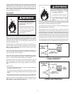
Contaminants in the gas lines may cause improper operation of
thegascontrolvalvethatmayresultinreorexplosion.Before
attaching the gas line be sure that all gas pipe is clean on the inside.
To trap any dirt or foreign material in the gas supply line, a drip leg
(sometimes called a sediment trap) must be incorporated in the
piping. The drip leg must be readily accessible. Install in accordance
with the “Gas Piping” section. Refer to the current edition of the
Natural Gas and Propane Installation Code (CAN/CSA B149.1).
FIGURE 14.
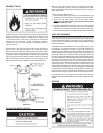
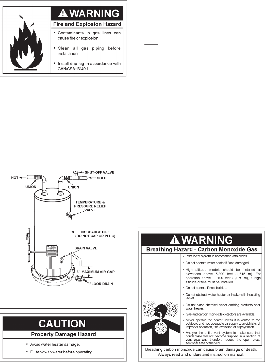
FILLING THE WATER HEATER
Never use this water heater unless it is completely full of water.
Topreventdamagetothetank,thetankmustbelledwithwater.
Watermustowfromthehotwaterfaucetbeforeturning“ON”gas
to the water heater.
Tollthewaterheaterwithwater:
1. Close the water heater drain valve by turning handle to the right
(clockwise). The drain valve is on the lower front of water heater.
2. Open the cold water supply valve to the water heater.
NOTE: The cold water supply valve must be left open when
the water heater is in use.
3. Toinsurecompletellingofthetank,allowairtoexitbyopening
nearesthotwaterfaucet.Allowwatertorununtilaconstantow
is obtained. This will let air out of the water heater and the piping.
4. Check all water piping and connections for leaks. Repair as needed.
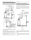
VENT PIPE ASSEMBLY
There are three parts of the vent pipe assembly that connect the
water heater exhaust (located on lower back side of water heater)
to inlet of the blower assembly (mounted on top of water heater) as
shown in Figure 1. These parts will need to be assembled according
to these instructions.
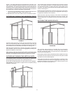
Assemble Vent Pipe Assemblies #1, #2 and #3 (See Figure 1) prior
to cementing. The preferred orientation of Vent Pipe Assembly #1
(Condensate U-Assembly) is shown in Figure 16. However this
assembly may be rotated to a different orientation as needed for the
specicinstallationrequirements.Notetherotationalorientationof
each part by marking a line several inches long across the joints.The
long tube of Vent Pipe Assembly #2 should be approximately vertical.
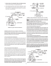
If it is found that either of the two pieces of pipe in Vent Pipe Assembly
#2aretoolongforpropert-up,thenremoveaslittlematerialas
possibletoimprovethet-up.Keepinmindthatthepipeswillinsert
slightly further into the elbows when cement is applied as it acts as
a lubricating agent. The vertical distance from the bottom of the
CondensateU-Assemblytotheoorthatsupportsthewaterheater
should be approximately 0.25” (0.64 cm), see Figure 16. Disassemble
the parts and cement back together using the alignment marks. After
the cement dries, attach the assembly to the blower and the water
heater exhaust using the supplied rubber boots and hose clamps.
A condensate trap is incorporated in the bottom of this vent pipe
assembly. See the CONDENSATE section of this manual for further
details.
VENTING