


24
VENT ATTENUATION ASSEMBLY
INSTALLATION INSTRUCTIONS
The Vent Attenuation Assembly (VAA) is designed to provide a
reduction in fan noise created in the blower wheel. This installation
of this VAA is optional. Review directions thoroughly prior to installing
the new VAA. Please contact the manufacturer of the water heater as
shown in the instruction manual with any questions or for additional
product support.
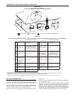
VENT ATTENUATION ASSEMBLY KIT PARTS LIST
The kit consists of the following items. If a part is missing, use the
contact information in the instruction manual to acquire missing
component(s).
•ventattenuationassembly
•exibletubing
•hosebarb
•hexplug(installedonVAA)
•instructionsheet
VENT ATTENUATION ASSEMBLY INSTALLATION
The VAA is designed for both vertical and horizontal installations.
The vertical installation does not require the additional hose barb
andexibletubing.However,thehorizontalinstallationwillrequire
thehosebarbandexibletubingtoreleasecondensatebuildup
from the VAA. See instructions and diagrams that follow for a more
detailed description.
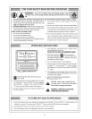
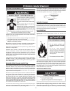
Breathing Hazard - Carbon Monoxide Gas
•
Do NOT block the holes in the hex plug of vent pipe
assembly #1.
•
Do NOT elevate any portion of the field supplied drain
line beyond the 1/2" adaptor above the adaptor. This
must be true for entire length of the drain line including
the exit into an appropriate drain
.
•
Condensate lines must be free and clear of debris and
must not allow back flow through drain line. Condensate
lines must be able to flow freely to an appropriate drain.
•
Do not allow condensate lines to become crimped closed.
•
Analyze entire vent system to make sure that condensate
will not become trapped in a section of vent pipe and
therefore reduce open cross sectional area of vent.
Breathing carbon monoxide can cause brain damage or death.
Always read and understand instruction manual.
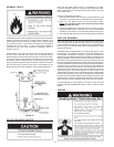
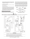
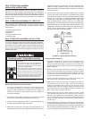
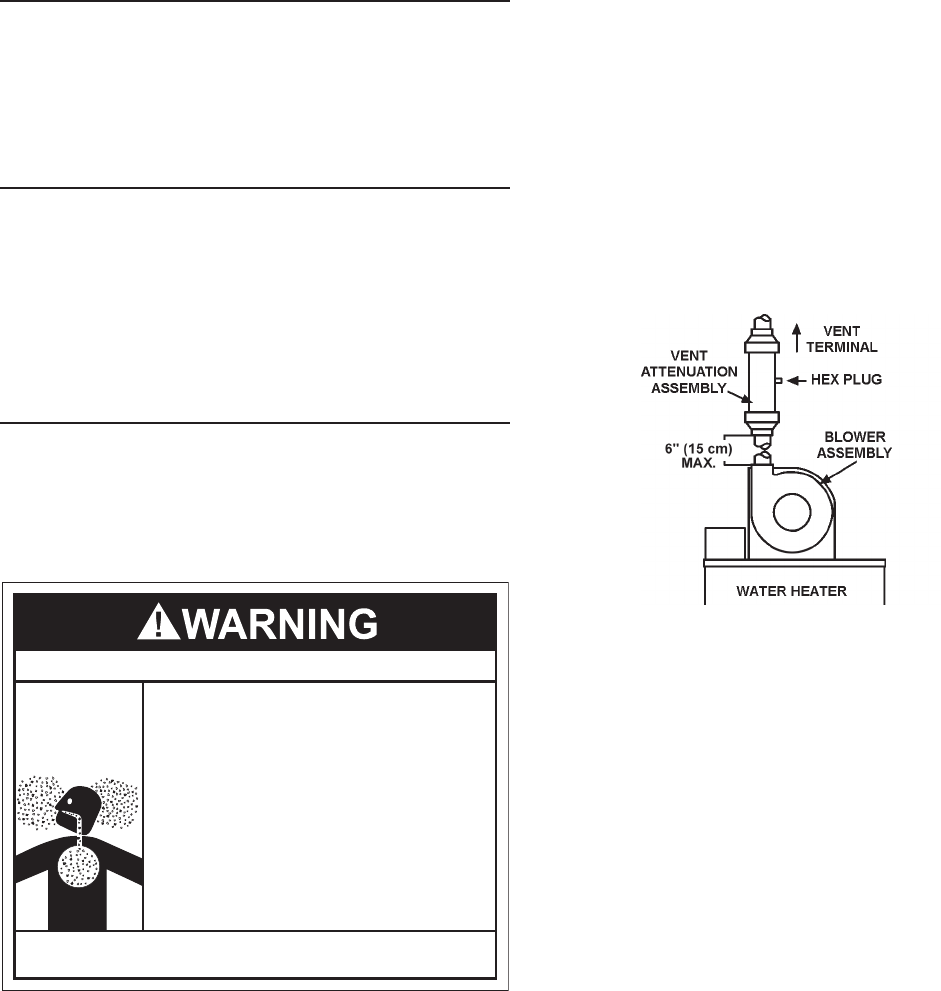
Vertical VAA Installations (Recommended)
1. The VAA is designed to accept two inch PVC pipe into
the adapters on both ends. The VAA can be installed to the
pipingfromeitherside(thereisnospecicinletoroutlet).For
optimum performance, install VAA as close as possible to
the blower assembly.
2. Followingtheventpipemanufacturer’sinstruction,glue the
two inch PVC pipe coming from the blower into the VAA.
3. Perform the same sequence on the PVC pipe coming from the
exhaust side (vent terminal side) of the VAA.
4. Make sure the VAA and vent pipe is supported securely to a
permanentxture(studorwall).Usestandardsupportstraps(not
supplied with kit) that may be found at a local hardware store.
Failure to properly support the VAA and the surrounding vent
pipe could create a hazardous situation. DO NOT puncture any
surface of the VAA.
5. Conrmthatthehexplugissecurelyinstalledinthe1/2”tting
found on the center of the VAA pipe. It is imperative that the plug
is secure and air tight to prevent any combustion gases escaping
into the room. If the plug is not securely tightened, remove and
reinstallusingTeontape onthe threads.Since neitherhose
barbnorexibletubingisusedonthe VAA,anyunusedopen
barbttingsonventpipeassembly#2needtobepluggedusing
break-away plugs. Once installed along with the rest of the vent
conguration,makesuretooperatetheunitthroughatleastone
heat up cycle to ensure there is no leakage around the plug or
any joints of the VAA or vent pipe system.
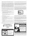
FIGURE 22: Typical Vertical Installation
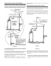
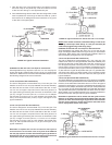
Horizontal VAA Installations
1. The VAA is designed to accept two inch PVC pipe into the
adapters on both ends. The VAA can be installed to the
piping from either side (there is no specific inlet or outlet). For
optimum performance, install VAA as close as possible to the
blower assembly.
2. Followingtheventpipemanufacturer’sinstruction,gluethe
two inch PVC pipe coming from the blower into the VAA. Make
sure the 1/2” fitting is on the bottom side of the VAA. This will
be used to run the condensate hose to a suitable drain. See
typical vent installation in Figure 23.
3. Perform the same sequence on the PVC pipe coming from
the exhaust side (vent terminal side) of the VAA.
4. Make sure the VAA and vent pipe is supported securely to
a permanent fixture (stud or wall). Use standard support
straps (not supplied with kit) that may be found at a local
hardware store. Failure to properly support the VAA and the
surrounding vent pipe could create a hazardous situation. DO
NOT puncture any surface of the VAA.
5. Remove hex plug from the center pipe of the VAA. Locate
the hose barb and install into the 1/2” fitting on the center of
the VAA. Using Teflon tape on the threads, install hose barb
into 1/2” fitting securely. It is imperative that the hose barb is
secure and tight to prevent any combustion gases escaping
into the room.
6. Locateexibletubing.Slideoneendoftubeoverthehosebarb
located on the center pipe of the VAA. The ridges on the hose barb
should prevent the tube from sliding off, however, to ensure there
are no leaks and possible dislocation from hose barb, use a wire
tie or hose clamp (not supplied with kit) and secure.