


14 / Supplement S1400
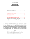
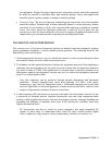
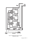
4. Setting DPC Power Jumpers.
If the DPC is a Model 3335 or 3310, jumpers W1A and W1B on
the System Interconnect Board must be removed to isolate the chassis connection from the
24V RET connection (see Figure 8). If it is a Model 3330, jumpers W1A, W1B and W1C on the
System Interconnect Board must be removed. Series 3308 Gas Flow Computers, if used with
these systems, provide an isolated instrument ground without setting jumpers.
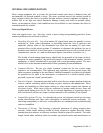
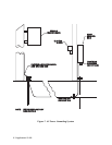
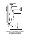
Multiple Clusters of DPC Cabinets Powered by Local Supplies
A cluster consists of two or more DPC cabinets that may be grouped together as shown in Figure
9. Several such clusters performing related functions in the same facility make up a multiple
cluster system. The following procedures apply:
1. Grounding for DPC Cabinet Cluster using Local Supply.
The instrument ground (24VRET
terminal) of each DPC in a cabinet must connect to a terminal block within that cabinet that
is electrically isolated from the cabinet frame. This terminal block must provide termination
for all instrument grounds within that cabinet and include termination for a multistranded,
insulated, #4 gauge wire (or greater) that will connect to the same termination point to other
cabinets of that cluster, and to the 24VRET terminal of the local power supply.
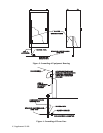
2. Routing of Cluster Grounds.
The instrument grounds (isolated terminal) from each cabinet
cluster must connect to each other and then to a single wire that connects to the zero
reference point of the facility. This wire should be #4 gauge minimum (multistranded and
insulated) and be contained in a metal conduit (pipe). A heavier stranded #4/0 gauge could
be used to connect each cluster to the zero reference point while the #4 wire instrument
grounds could be locally terminated to the #4/0 wire. The conduit containing this wire must
also be connected by bonding strap to the cabinet and facility frame as described in the NEC.
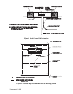
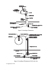
3. AC Power Source.
The 24 Vdc power supply of each cluster requires a 120 Vac power
source. The ac power terminals of this supply are identified in Figure 8. The 120 Vac wiring
for this supply must be contained in cable trays along with the power grid grounding wire.
Figure 9 illustrates the cable tray layout and grounding points of a typical facility. The frame
of each cabinet and each DPC chassis a cluster must be connected with bonding strap at
points specified in the NEC.
4. Setting DPC Power Jumpers.
If the DPC is a Model 3335 or 3310, jumpers W1A and W1B on
the System Interconnect Board must be removed to isolate the chassis connection from the
24V RET connection (see Figure 8). If it is a Model 3330, jumpers W1A, W1B and W1C on the
System Interconnect Board must be removed. Series 3308 Gas Flow Computers and
Correctors, if used with these systems, provide an isolated instrument ground without setting
jumpers.
References:
1. Grounding for the Control of EMI; Hugh W. Denny;
Don White Consultants, Inc. (c) 1983, 1st Ed.
2. IEEE Std. 518-1982
3. ANSI/IEEE Std. 142-1982