


CI-9110 3-5 Board Setup
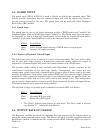
3.5 GUARD INPUT
The guard input (TB1-5 & TB1-6) is used to Enable or Inhibit the command input. This
feature provides assurance that the command input will read its signal only during a
security period selected by the user. The guard input can be used with either Analog or
Raise/Lower (R/L) models.
3.5.1 Guard Logic
The guard logic can be set for logical operation so that a TRUE-state signal “enables” the
Command input, while a FALSE-state signal “inhibits” it. The Guard input logic can also be
set internally so that it is kept ON continuously; in this mode the Command input will be
“enabled” at all times. Switch SW2-6 is used to set the guard mode as follows:
SW2-6
Guard Mode
Open Active (Guard signal must be in TRUE state to accept input)
Close Inactive (All inputs accepted)
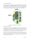
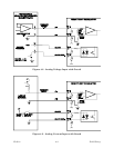
3.5.2 Static or Dynamic Guard Input
The Guard input may be set to operate in a static or dynamic mode. The static mode, which
can be used with either Analog or Raise/Lower command signals, allows the output to
respond to a Command signal only when the Guard terminal is in a TRUE state.
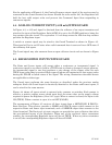
The dynamic mode, which is only available with Raise/Lower models, responds to the
simultaneous transition of two pulse-type signals. Consequently, the output will only
change when a guard pulse and a command pulse (either a raise or lower) occur at the same
moment. Furthermore, both pulses must remain TRUE until the actuator output change is
complete. If either a guard or command pulse is not completed before the specified time, the
pressure output will be held at its last value until a new change occurs. This arrangement
can be used to obtain greater system security from extraneous signals and signal failure.
This feature should not be used with Analog models.
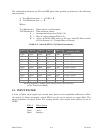
The selection of static or dynamic mode is obtained via switch SW2-1 as follows:
SW2-1
Guard Status
Close Dynamic (R/L type only)
Open Static (AI or R/L types) *
* The "Open" position must always be used when "Fail Zero" mode is selected
(see Section 3.7 - "Analog Failure Modes").
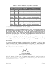
3.6 OUTPUT RATE OF CHANGE
The Regulator includes provisions for changing the time required by the stepper motor to
sweep the entire pressure output range. This feature, which is available on both Analog and
Raise/Lower models, is implemented by setting switches SW2-2 through SW2-5 as noted in
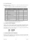
Table 3-3.