


Service 5-8 CI-9110
5. DMM #1 should read 4.995 V, ±.01 V
6. If the reading of step 5 is out of tolerance, adjust potentiometer R35 on CPU Board to
correct.
7. Recheck both points and readjust if required.
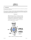
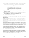
5.8.2 Current Output Span & Load
The current output circuitry is provided with two calibration adjustments. Potentiometer
R50 is used for span adjustment and R49 for load compensation. For these tests DMM #2
using the current measurement function is connected in series with a 250 ohm resistor load
as shown in Figure 5-3. The pushbutton switch is used to jump the load.
1. Adjust input test circuit for 4.995 V on DMM #1.
2. DMM #2 should read 20 mA. If necessary, adjust pot R50 to correct.
3. Press load pushbutton while observing DMM #2. If current reading increases, adjust
R49 CCW. If reading decreases, turn it CW. Repeat procedure until change is less than
±.02 mA.
4. Final reading should be 20 mA, ±.02 mA. If necessary, reset pot R50 and repeat
procedure.
5. Calibration is complete. Restore unit to normal operating status.
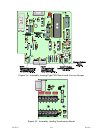
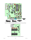
5.9 PCB REFERENCE DRAWINGS
Table 5-1 below provides part numbers and drawing references (Figures 5-4 through 5-7)
for the printed circuit boards provided with the Remote Set Regulator.
Table 5-1 - CPU Board & Termination Board Reference Table
Fig. Assembly Part # Pag
e
5-4 Assembly, Analog Type CPU Board w/ Current Output (12V) 389615-03-0
5-9
5-4 Assembly, Analog Type CPU Board w/ Current Output (24V) 389615-06-4
5-9
5-5 Assembly, Analog Termination Board 389644-01-3
5-9
5-6 Assembly, Raise/Lower Type CPU Board w/ Current Output (12V) 389613-03-7
5-10
5-6 Assembly, Raise/Lower Type CPU Board w/ Current Output (24V) 389613-06-1
5-10
5-7 Assembly, Raise/Lower Termination Board 389616-01-0
5-10