


CI-9110 7-1 Parts
Chapter 7
PARTS
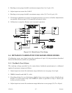
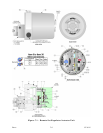
7.1 MODEL 9110 MAIN PARTS
Parts Referenced in Figure 7-1
Item Description Part Number
1 Housing 390701-01-7
2 O-Ring, Size – 161 316135-12-7
3 Remove Setpoint Cover 389385-02-6
4 Motor Support Assembly 390724-01-7
5 Clutch Assembly 390692-01-8
6 Potentiometer 390739-01-4
7 Socket Head Screw, 6-40 x 1/8 282403-00-0
8 Right Hand Stop 390736-02-3
9 Left Hand Stop 390736-01-5
10 Shaft & Pot. Support Assembly 390723-01-0
11 Shoulder Screw, 10-32 x 1-3/16 390726-01-0
12 Gear, 144 Teeth, 63 Pitch 390684-01-5
13 Screw, 2-64 x 3/16 FH 237603-00-4
14 Shaft Assembly 396405-01-0
15 Sleeve, Output Shaft 390695-01-7
16 Motor Assembly:
12 V dc type 390738-01-8
24 V dc type 390738-02-6
17 Bracket, Terminal Block 390080-01-2
18 Clamp, Pot. 390090-01-8
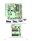
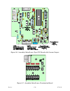
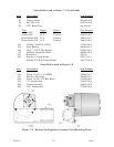
19 PC Board Assembly, 624-II Remote
Raise/Lower Termination Board:
12 & 24 Vdc Discrete Input Versions 389616-01-0
12 & 24 Vdc Analog Input Version 389644-01-3
20 Gear, 68 Teeth, 64 Pitch 390735-01-9
21 Jumper, Remote Regulator 390761-01-0
23 Screw, 4-40 x 3/1 Pan Head 374600-03-1
24 Cable Tie, Self Clinching (Not Shown) 308708-00-8
29 Bushing, 3/4" ID Wire 390104-01-9
30 Cable, Pot. 390404-01-2
33 Screw, 10-32 x 3/8 PH 374602-06-9
34 Screw, 10-32 x 1/2 PH 374602-08-5
35 Screw, 10-32 x 3/4 PH 374602-12-3
36 Screw, 10-32 x 1-1/2 PH 374602-24-7
38 Screw, 6-32 x 3/16 PH 374601-03-8
39 Screw, 6-32 x 5/16 PH 374287-01-5
42 Lockwasher, #10 235638-00-5
43 Screw, 8-32 x 5/16 HH 374616-01-9
44 Cup Washer, #8 387445-01-3