


Supplement S1400 / 7
TYPES OF EARTH GROUNDS
A common misconception of a ground is that it consists of nothing more than a metal pipe driven
into the soil. While such a ground may function for some applications, it will often not be suitable
for a complex system of sophisticated electronic equipment. Conditions such as soil type,
composition and moisture will all have a bearing on ground reliability.
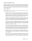
A basic ground consists of a rod 3/8 in. diameter with a minimum 8 ft. length driven into
conductive earth to a depth of about 7 ft as shown in Figure 1. Number 14 AWG solid copper wire
(or larger) should be used for the ground wire. The end of the wire should be clean, free of any
coating, and fastened to the rod with a clamp. A cover or housing should be installed over the
ground connection to protect it from the weather and the environment.
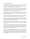
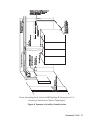
Where soil conditions are poor, additional ground rods can be driven into the earth at various
distances and strapped together. Figure 2 shows an overhead layout of a ground bed used for
a gas metering station. Other arrangements (not shown) consist of a buried wire counterpoise
or a 3 ft. square copper plate.
A ground should be tested for conductivity before putting it into service. Details on on this test
are described in the NATIONAL ELECTRIC CODE HANDBOOK. Once a reliable ground has
been established, it should be tested on a regular basis to preserve system integrity.
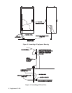
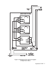
Instrument enclosures, measuring devices, metal process vats, metal piping, and other
associated mechanical and electrical devices should all be grounded. The method of grounding
an instrument rack is shown in Figure 3. In this application the ground lead typically attaches
to a ground bus that is common to all equipment in the rack.
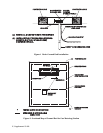
For applications employing equipment that communicates over telephone lines, a lightning
arrestor must be provided at the point where the communication line enters the building as
shown in Figure 4. The ground terminal of this arrestor must connect to a ground rod and/or a
buried ground bed.
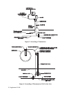
Applications that use transmitters or transducers require grounding and shielding. In Figure
5, the ground conductor feeds through the electrical conduit and connects to the ground screw
of the transmitter even though the support pipe is grounded. However, if the transmitter uses
shielded wiring for its signal output, the shield should not be grounded at the transmitter. For
maximum signal accuracy, the shield should only be grounded at one point in the system,
typically at the input of the associated equipment.
Gas lines also require special grounding considerations. If a gas meter run includes a
thermocouple or RTD sensor installed in a thermometer well, the well (not the sensor) must
connect to a gas discharge-type lightning arrestor as shown in Figure 6. A copper braid, brazed
to the thermal well, is dressed into a smooth curve and connected to the arrestor as shown. The
curve is necessary to minimize arcing caused by lightning strikes or high static surges. The path
from the lightning arrestor to the ground bed should also be smooth and free from sharp bends
for the same reason.