


Introduction 1-6 CI-5450
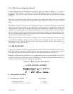
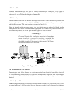
1.2.4 Raise/Lower Regulator Model
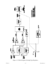
A block diagram for the Raise/Lower Regulator model is shown in Figure 1-3. It will be
noted that this diagram is similar to the Analog Regulator except for the input circuit ar-
rangement. This circuit contains Raise, Lower and Guard input circuits which are opto-
isolated.
The outputs of all three opto-isolators are applied to a logic circuit that checks the status of
the three signals and determines whether the output will be in a Raise, Lower or Guard
mode.
Each Raise and Lower input may be configured to accept a continuous or pulse incremental
signal. The continuous signal is a dc input that, when switched to an ON state, allows the
stepper motor to rotate in the proper direction; when switched to an OFF state, it stops the
stepper motor and maintains a corresponding output value. The pulse incremental signal
can be a single dc pulse or a pulse train input that causes stepper motor to change the out-
put by an incremented amount. The amount of the output increment is determined by the
settings of the configuration switches.
The outputs of all three opto-isolators in Figure 1-3 are status signals that, when processed
by the CPU, establish a pressure output value that corresponds to the input signals. The
remainder of the circuitry shown in the illustration operates in the same manner as
described for Analog Regulators.
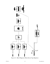
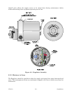
1.3 DATA PLATE
A data plate affixed to the Remote Set Regulator lists the instrument model, serial number
and other relevant information. The features and options present in an instrument can be
determined by comparing its model number to the model breakdown of Table 1-A.
Remote Set Regulators certified for use in hazardous areas will include the seal of the
certifying laboratory on the data plate. Certification will also be indicated as an element of
the instrument model number listed on the data plate.
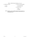
Table 1A - Model Number Breakdown
- SAMPLE MODEL NUMBER -
# = BASE MODEL NUMBER
A = ELECTRICAL INPUT B = POWER
1 = Raise/lower Input 1 = 12V dc
2 = Analog Input (1-5V or 4-20 mA) 2 = 24V dc