


CI-9110 5-7 Service
2. Reading on test gauge should be minimum range value (3 or 6 psi), ±5%.
3. Adjust input test circuit for 5.000 V.
4. Reading on test gauge should be maximum range value (15, 27 or 30 psi), ±5%.
5. If electronic calibration is correct but output pressure is in error, no further adjustments
are possible. Refer to topic 5.2 for possible pneumatic faults.
6. Calibration is complete. Restore unit to normal operation.
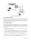
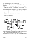
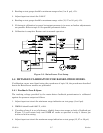
Figure 5-3 - Raise/Lower Test Setup
5.8 DETAILED CALIBRATION FOR RAISE/LOWER MODEL
If calibration errors were found using the procedures of topic 5.6, the procedures described
herein for Raise/Lower models are performed.
5.8.1 Feedback Zero & Span
The tracking voltage provided by the motor-driven feedback potentiometer is calibrated
against the pressure output as follows:
1. Adjust input test circuit for minimum range indication on test gauge (3 or 6 psi).
2. DMM #1 should read 0.995 V, ±.004.
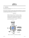
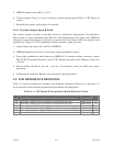
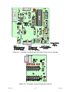
3. If reading of step 2 is out of tolerance, slightly loosen two screws on body of feedback pot
(Figure 5-1) and rotate body until DMM #1 reads as specified in step 2. Secure pot
screws to lock in setting.
4. Adjust input test circuit for maximum range indication on test gauge (15, 27 or 30 psi).