


Field Wiring 4-4 CI-9110
For the application of Figure 4-2, the Carrier Presence output signal of the receiver may be
connected to the Guard terminal as shown. Should the tone carrier fail, the Regulator will
hold the last valid output value and prevent the Command Input from responding to
extraneous signals.
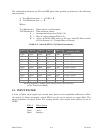
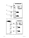
4.4 ANALOG CURRENT INPUT (4-20 mA) WITH GUARD
In Figure 4-3, a 4-20 mA signal is obtained from the collector of an output transistor and
wired to the input of the Regulator. Switch SW2-8 is set to the CLOSE position to bring the
loop resistor into the circuit. The equivalent 1-5 volt drop across the 250 ohm loop resistor
provides the Regulator input.
A switch or contact signal may be wired to the Guard Terminal as shown in Figure 4-3.
This signal will be in an ON state when valid command data is sent and in an OFF state if
the telemetry link opens.
The Guard signal may also emanate from an open collector circuit such as shown in Figure
4-2
4.5 RAISE/LOWER INPUTS WITH GUARD
The Raise and Lower inputs will accept either a continuous or incremental signal. A
continuous signal is one that is held in a TRUE state to obtain a change of output pressure.
An incremental signal is one that produces a step change of the output value for each
TRUE input pulse that is received. Both types of inputs will maintain the last output value
during the FALSE or failed states of the signal. The wiring illustrations described herein
are applicable to either type.
The Guard input performs the same function as described under the previous analog
subtopics. Since the Guard input is electrically identical to the Raise and Lower inputs, it
can be wired in the same manner.
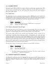
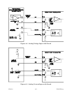
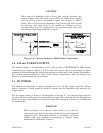
Figure 4-4 shows all inputs wired to external relay contacts or switches. Each contact is
wired to a positive voltage source which must have the same value as the supply voltage
required to power the Regulator (12 or 24 V type). When a contact is closed, the input is set
ON (TRUE). When a contact is open, it is set OFF (FALSE).
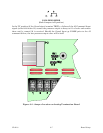
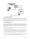
The arrangement of Figure 4-5 receives all three inputs from a METATONE B FSK Tri-
State Receiver. This receiver provides a MARK and SPACE output which connect to the
respective Raise and Lower input terminals, and a CARRIER output that connects to the
Guard terminal. The Receiver's tri-state outputs are provided as open collectors that drive
the opto-isolated inputs of the Regulator. When any of the receiver's driver transistors
conduct, the corresponding Regulator input will be set TRUE. When any driver transistor
is cut off, the corresponding Regulator input will be set FALSE.