


CI-9110 3-1 Board Setup
Chapter 3
BOARD SETUP
3.1 USING OPTION SWITCHES
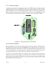
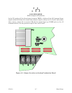
Two switch assemblies (SW1 and SW2) are used to set options and select ranges. These
switches are located on the CPU Board as shown in Figure 3-1. Each assembly contains
eight (8) miniature SPST switches. The individual switches of each package are identified
as subsets of the main switch, e.g., SW1-1, SW1-2, etc.
Two types of switch assemblies are used for Regulators. One type uses cradle switches,
while the other uses slide-type switches. The operation of each type differs as follows:
Cradle Switches with OPEN Designation
:
OPEN side pressed down = OFF (open circuit)
Numbered side pressed down = ON (closed circuit)
Slide Switches with ON Designation
:
Set in direction of ON arrow = ON (closed circuit)
Set in opposite direction of arrow = OFF (open circuit)
The switch assemblies are fragile and require careful handling. Use a small, blunt object
such as a miniature screwdriver to set the switch positions. Do not use pencils, ballpoint
pens, or extremely sharp objects for this purpose.
WARNING
When starting a unit for the first time, all switch options must be set before
any power is applied. Improper switch settings can cause improper
operation or dangerous control situations that could damage process
equipment and property, or cause injury to persons.
NOTE
Attempting to change settings of any switch (excluding SW2-6 and SW2-8)
while the unit is on line will not
produce a change of configuration.
Although the switches have been set, the configuration will not take effect
until the power applied to the Regulator has been turned OFF and, after a
moment, turned back ON again.
If switch settings are changed without turning the power OFF, the present
on-line configuration will remain in effect until the unit is turned OFF and
powered up again.