


Service 5-6 CI-9110
5. If above readings are within stated specifications, stop! No calibration is required.
Restore instrument to normal operation. Otherwise, proceed to topic 5.7 or 5.8 as
required.
5.7 DETAILED CALIBRATION FOR ANALOG MODEL
If calibration errors were found in topic 5.6, the procedures described here for Analog
models are performed.
5.7.1 Feedback Zero & Span
Precision voltage of an input test circuit is used to calibrate the zero and span as follows:
1. Adjust input test circuit for 1.000 V output.
2. DMM #1 should read 0.995 V, ±.004 V.
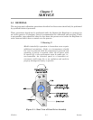
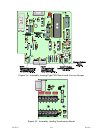
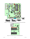
3. If reading of step 2 is out of tolerance, slightly loosen two screws on body of feedback pot
(Figure 5-1) and rotate body until DMM #1 reads as specified in step 2. Secure pot
screws to lock in setting.
4. Adjust the input test circuit for 5.000 V.
5. DMM #1 should read 4.995 V, ±.004 V
6. If the reading of step 5 is out of tolerance, adjust potentiometer R35 on CPU to correct.
7. Recheck both points and readjust zero and span if required.
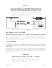
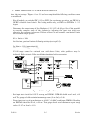
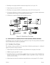
5.7.2 Current Output Span & Load
The current output circuitry is provided with two calibration adjustments. Potentiometer
R50 is used for span adjustment and R49 for load compensation. For these tests, DMM #2
(used as a milliammeter) is connected in series with a 250 ohm load resistor as shown in
Figure 5-2. The pushbutton switch is used for load testing.
1. Adjust input test circuit for 5.000 V.
2. DMM #2 should read 20 mA, ±.02 mA. If necessary, adjust pot R50 to correct.
3. Press load pushbutton while observing DMM #2. If current reading increases, adjust
R49 CCW. If reading decreases, turn it CW. Repeat procedure until change is less than
±.02 mA.
4. Final reading should be 20 mA, ±.02 mA. If necessary, reset pot R50 and repeat the
procedure.
5.7.3 Pressure Output Check
1. Adjust input test circuit for 1.000 V.