


Board Setup 3-2 CI-9110
3.1.1 Switch Functions
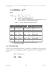
The Regulator assembly is configured by two, eight-switch packages which perform the
functions listed in Table 3-1.
Table 3-1 - Regulator Assembly Switch SW1 & SW2 Functions & Settings
Switch
Label
Switch
Function
Page
Ref.
*
Your Setting
**
Your Notes
SW1-1 R/L % per pulse increment 3-4
SW1-2 R/L % per pulse increment 3-4
SW1-3 R/L % per pulse increment 3-4
SW1-4 R/L % per pulse increment 3-4
SW1-5 R/L % per pulse increment 3-4
SW1-6 Not Used None
SW1-7 Not Used None
SW1-8 Input Filter 3-4
SW2-1 Guard (Dynamic/Static) 3-5
SW2-2 Actuator Output Rate of Change 3-6
SW2-3 Actuator Output Rate of Change 3-6
SW2-4 Actuator Output Rate of Change 3-6
SW2-5 Actuator Output Rate of Change 3-6
SW2-6 Guard (Active/Inactive) 3-5
SW2-7 Not Used None
SW2-8 Analog Input (V or I) 3-2
* Record your switch settings (ON or OFF) here for future reference.
** List your corresponding switch functions or values here.
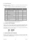
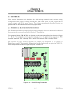
3.2 ANALOG INPUT MODELS
Initially, it will be necessary to check the position of switches SW1-1 through SW1-5. These
switches must be set to their OPEN positions to properly disable the functions associated
with Raise/Lower models. The other uses of these switches are described under topic 3.3.
Analog models can be set to accept a 4-20 mA or 1-5 V dc signal at the Command Input.
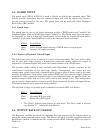
Switch SW2-8 selects these outputs as follows:
SW2-8
Analog Range
Close 4-20 mA dc
Open 1-5 V dc
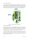
3.3 RAISE/LOWER INPUT MODELS
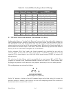
Raise/Lower Actuator models can be set for continuous or incremental-type input signals
via switches SW1-1 through SW1-5. The switch positions are shown in Table 3-2. The
switch selections are described as follows: