


CI-9110 5-5 Service
5.6 PRELIMINARY CALIBRATION CHECK
Once the test setup of Figure 5-2 or 5-3 has been completed, the following conditions must
be established.
1. For all models, set switches SW1 (1-5) to OPEN for continuous operation, and SW2-6 to
OPEN to disable Guard circuit. For Analog models only, set SW2-8 to OPEN for 1 - 5 V
input.
2. Determine the output range of the Regulator (3-15, 3-27 or 6-30 psi). See if it is possible
to scan the complete range of the regulator by adjusting the input test circuit and
observing the pressure test gauge. If range of travel is not complete, mechanical limits
are less than output span or:
0% < Limits < 100%
At this time, position limits to following settings (see topic 5.3):
Lo Limit = -10% (approximately)
Hi Limit = +110% (approximately)
If full range cannot be obtained even with above limits, other problems may be
indicated. Refer to topic 5.2 for troubleshooting hints before proceeding.
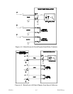
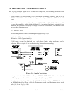
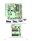
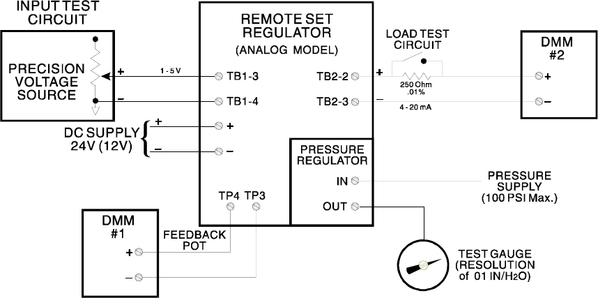
Figure 5-2 - Analog Test Setup
3. Set input test circuit for 0.995 V reading on DMM #1. DMM #2 should read 4 mA, ±.02
mA Test gauge should read minimum range value (3 or 6 psi), ±5.0%.
4. Press input test circuit push-buttons for 4.995 V, ±0.004 V reading on DMM #1. Reading
on DMM #2 should be 20 mA, ±.02 mA. Test gauge should read maximum output range
value (15, 27 or 30 psi), ±5.0%.