INSTALLATION, GENERAL
The Bayvue DV installation must ensure adequate combustion air and ventilation air is available for proper
stove operation. Refer to the venting section for further combustion air requirements. Installation must
conform to local codes and gas supplier restrictions. In the absence of local codes, an installation must
conform to the current National Fuel Gas Code which at the writing of this manual is ANSI Z223.1
(reference NFPA-54 for natural gas or reference NFPA-58 for propane products). In Canada, an
installation must conform to CAN/CGA-B149 code.
This appliance must be electrically connected and grounded in accordance with local codes, or in the
absence of local codes, with the current NFPA 70 National Electric Code or in Canada, with CSA C22.1
Canadian Electrical Code.
IT IS IMPERATIVE THAT THIS APPLICANCE’S CONTROL COMPARTMENT, BURNER, AND
CIRCULATING AIR PASSAGE WAYS ARE KEPT CLEAN AND CLEAR OF OBSTRUCTIONS.
ALWAYS PROVIDE FOR ADEQUATE COMBUSTION AIR AND ENSURE PROPER OPERATION
AT ALL TIMES. PROVIDE ADEQUATE CLEARANCES AROUND AIR OPENINGS AND
NECESSARY ACCESSIBILITY FOR ROUTINE OPERATION AND SERVICE. NEVER OBSTRUCT
ANY OPENINGS ON THIS APPLIANCE OR NEVER OBSTRUCT THE DIRECT VENT
TERMINATION ON THE EXTERIOR OF THE BUILDING.
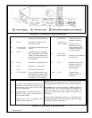
MINIMUM CLEARANCES TO COMBUSTIBLES MUST BE MAINTAINED DURING
INSTALLATION. THE HEATER MUST HAVE ADEQUATE SPACE FOR PROPER OPERATION
AND SERVICING. MAINTAIN MINIMUM CLEARANCES AND VENT/AIR INTAKE PIPE
CLEARANCES.
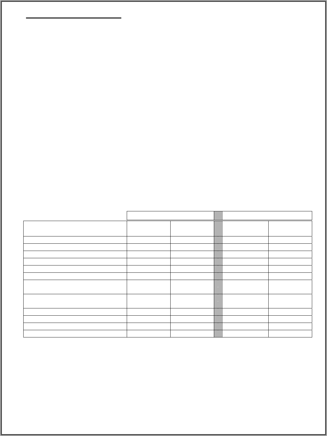
TABLE 1: BAYVUE DV SPECIFICATIONS
BAYVUE DV-46
BAYVUE DV-30
NATURAL
GAS
PROPANE
NATURAL
GAS
PROPANE
Altitude 0 - 4500’ 0 - 4500’ 0 - 4500’ 0 - 4500’
Manifold pressure 3.5” W.C. 10” W.C. 3.5” W.C. 10” W.C.
Minimum Inlet Gas Pressure 4.5” W.C. 11” W.C. 4.5” W.C. 11” W.C.
Maximum. Inlet Gas Pressure 7.0” W.C. 14.0” W.C. 7.0” W.C. 14.0” W.C.
BTU Input Rating (High) 46,000 46,000 BTUH 32,000 30,000 BTUH
BTU Input Rating (Low) 29,000 34,500 BTUH 21,000 21,500 BTUH
*Efficiency with fan (steady
state)
35,700 36,800 BTUH 24,000 23,100 BTUH
*Efficiency no fan (steady
state)
37,200 39,100 BTUH 22,800 22,000 BTUH
*A.F.U.E. 68.77% 70.67% 60.19% 62.22%
Front Burner Orifice 55 DMS 69 DMS 57 DMS 70 DMS
Middle Burner Orifice 45 DMS 55 DMS 50 DMS 59 DMS
Rear Burner Orifice 40 DMS 53 DMS 45 DMS 55 DMS
*ANSI standards are SAFETY STANDARDS not PERFORMANCE STANDARDS. A.F.U.E.
(efficiency standards) and efficiency test protocol are established by the U. S. Department of Energy.
PRESSURE TESTING
Version 1.0h
5
This appliance MUST BE isolated from the gas supply piping system during any pressure testing of the
gas supply piping system at test pressures equal to or less than ½ pounds per square inch gauge (psig) (3.5
kPa or 14” W.C.) Isolate the appliance by closing the manual shutoff valve during pressure testing.
Failure to isolate the appliance will cause damage and can require replacement of the SIT 820 NOVA mV
gas control valve. If test pressures will be in excess of ½ psig, then the SIT 820 NOVA mV gas control
valve must be disconnected from the gas supply line. Refer to FIGURE 27 for SIT 820 NOVA mV valve
information.


