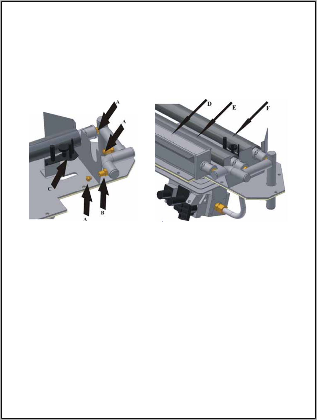
MAIN ORIFICES
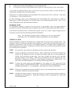
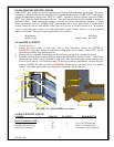
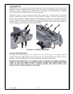
FIGURE 25, left view, illustrates the front burner spud orifice (Item A) unthreaded from the orifice holder
(Item B). Do not over tighten the orifice spud. Do not leave the orifice spud finger tight as gas may leak
from the loose fitting. Note that the front, middle, and rear spud orifices are identified as Item A. FIGURE
25 also shows the pilot assembly (Item C) for reference purposes.
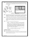
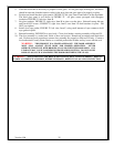
FIGURE 25, right view, shows the burner assembly with a partial view of all three burners; front burner
(Item D), middle burner (Item E), and the rear burner (Item F) installed. Be careful, when removing
burners. The front burner is uniquely different but the middle and rear burner look very similar. When any
one or all of the burners are removed, ensure they are marked from the spot they were taken and returned to
the same position. The burners are NOT interchangeable and must be placed in the proper position to
prevent sooting from occurring and to ensure proper burning.
FIGURE 25: BURNER ASSEMBLY
GAS FLAME INSPECTION
The flames will be blue during the first 5 minutes or so but over the period of 15 minutes they will
gradually turn yellow. Flame intensity and the glowing logs vary with the specific type of fuel and venting
conditions. Refer to FIGURE 5d for a picture that shows a proper flame for natural gas.
Version 1.0h
38
IMPORTANT INFORMATION: IT IS NORMAL FOR GAS PRODUCTS, FABRICATED FROM
STEEL, TO GIVE OFF SOME EXPANSION AND/OR CONTRACTION NOISES DURING THE
START UP OR COOL DOWN CYCLE. SIMILAR NOISES ARE FOUND WITH YOUR
FURNACE HEAT EXCHANGER OR CAR ENGINE.


