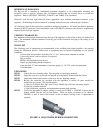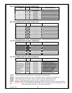
MINIMUM CLEARANCES
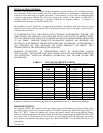
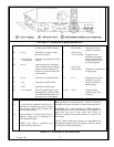
The Bayvue DV is installed by maintaining minimum clearances to all combustibles including any
projections such as shelves, window sills, or fireplace mantles that are located above or around the
appliance. Refer to FIGURE 2, FIGURE 3, TABLE 2, and TABLE 3 for clearances.
Sidewalls, both left and right sidewalls where applicable, must maintain minimum clearances to the
appliance. Overheating of sidewall material or framing material can occur without proper clearance.
All clearances listed in this manual are considered minimum clearances. All actual installation appliance
clearances MUST conform to local installation codes AND MUST conform to any clearance requirements
imposed by the local gas supplier.
CEILING CLEARANCES
The minimum ceiling height measured from the top of the appliance to the ceiling is thirty six inches (914
mm). The minimum clearance measured from any part of the horizontal vent pipe to the ceiling is one
inch (25 mm).
TOOL LIST
The following tools or equipment are recommended to the certified professional installer to be required
during the installation process. Other tools or equipment may be required depending on site specific
conditions:
- Various open end wrenches, including
7/16”, ½”, 9/16”, and crescent wrenches as needed.
- Various nut drivers’ and torx drivers, as required.
- Pipe wrenches.
- Phillips and flat bladed screw drivers.
- Proper gas pipe fitting sealant compound.
- Leak test fluid “U” tube manometer or pressure gauge (0 – 16” WC scale) test equipment.
- Volt/ohm meter.
UNPACKING
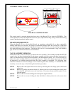
STEP 1 Unbolt the stove from the pallet. Discard pallet and packaging material.
STEP 2 Open the stove door on the unit and unpack all components located inside the firebox.
STEP 3 Inspect the interior and exterior of the stove for any shipping damage.
STEP 4 Review the materials list provided with the appliance to ensure all parts needed for
installation are present. This should include:
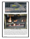
a) One set of ceramic fiber logs, (total 3 logs). Handle logs with care, extremely fragile.
b) One bag of ember material.
c) One installation, operation, and maintenance manual with warranty.
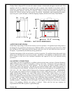
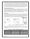
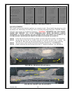
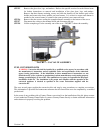
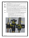
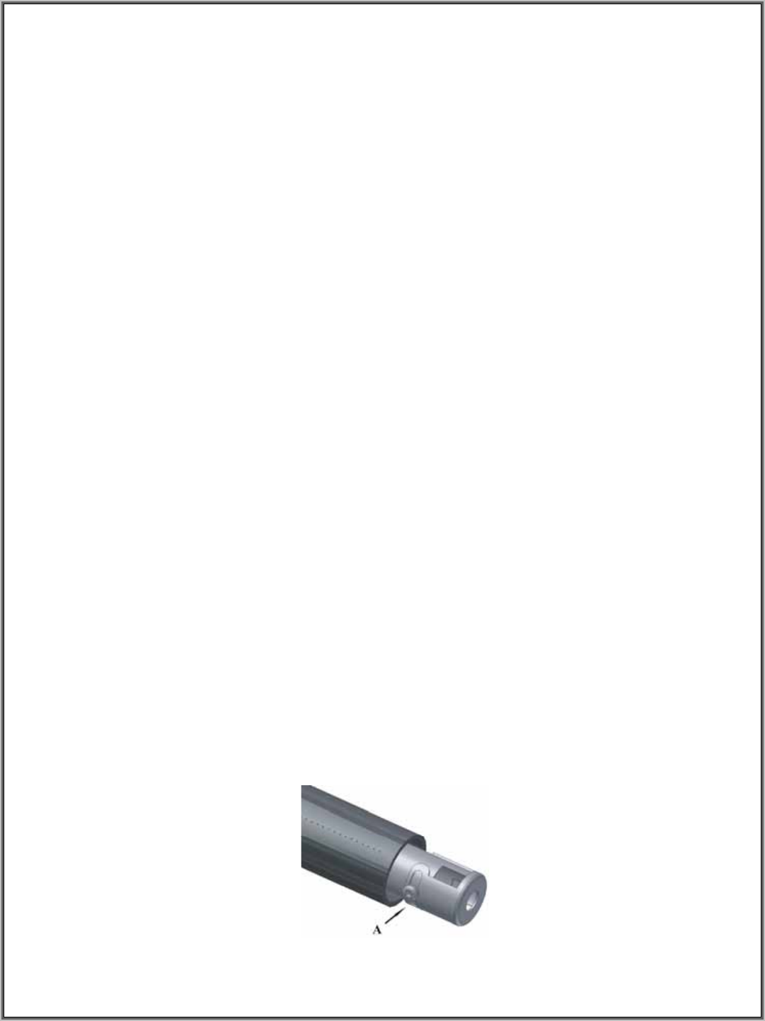
STEP 5 Verify the adjustable air shutter setting is correct per TABLE 4. FIGURE 4 shows the air
shutter welded into the end of each burner. There are three air shutters to be checked.
FIGURE 4, item A shows the location of the air shutter locking screw, if adjustment is
required.
Version 1.0h
9
FIGURE 4: ADJUSTABLE BURNER AIR SHUTTER


