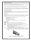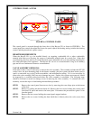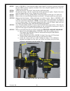
STEP 5 Refer to FIGURE 8. Ensure that the rubber gasket (Item D) is properly positioned and install
the new HI/LO pressure regulator assembly to the valve using the supplied screws (Item E).
Tighten screws securely.
STEP 6 Attach the enclosed "conversion" label near the certification label.
STEP 7 Re-attach all wiring to the fan control knob and the piezoelectric igniter. Replace the access
panel and tighten the two screws. Replace the control knobs.
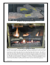
STEP 8 Remove the door, the logs, and the embers, noting the position of each log as it is removed.
STEP 9 Remove the two screws holding the ember tray in place. Lift up the ember tray and remove.
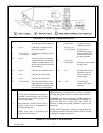
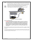
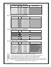
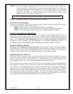
STEP 10 Remove the three burners. Mark each burner as to their location. Refer to FIGURE 4 and
TABLE 4 for proper air shutter adjustment for each burner. Adjust each burner’s air shutter to
meet fuel conversion requirements. NOTE: Use the shank of an appropriately sized drill bit
as an air shutter gauge. Pass the gauge through both sides of the air shutter, adjust and lock
the shutter removing the gauge when finished making adjustments.
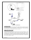
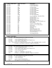
STEP 11 Use a 3/8-inch (10mm) wrench to remove and discard the burner spud orifices. Place the new
burner spud orifices in the appropriate location per the conversion kit instruction or refer to
page 12 for the proper location of each labeled burner spud orifice.
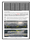
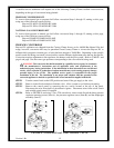
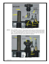
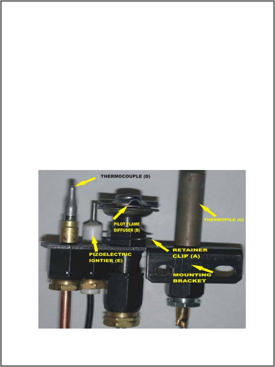
STEP 12 Remove and replace the pilot gas orifice located in the PILOT FLAME DIFFUSER BODY.
a) Remove the pilot flame diffuser (FIGURE 9, Item B) by pulling up on it.
The retainer clip (FIGURE 9, Item A) should release the pilot flame diffuser
with a light pulling motion.
b) Remove the pilot gas orifice (FIGURE 10, Item F) by using a 5/32 hex head
wrench (Allen wrench) placed in the top of the pilot gas orifice.
c) Verify the correct pilot gas orifice number per page 14 kit definitions.
Reinstall and tighten the new pilot gas orifice and replace the pilot flame
diffuser by reinserting it into the retainer clip.
Version 1.0h
16
FIGURE 9: PILOT VALVE (back side)


