


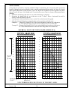
VENT GRAPHS
Vent graphs are provided to assist the certified installer in determining the correct horizontal and vertical
lengths of chimney pipe to be utilized for both a specific application and the specific fuel that will be used
with a specific Bayvue DV model fireplace. Note: The Bayvue DV 46 and DV 30 have separate vent charts
both per model and type of fuel being used. Ensure that the correct Chart is referenced during installation
planning.
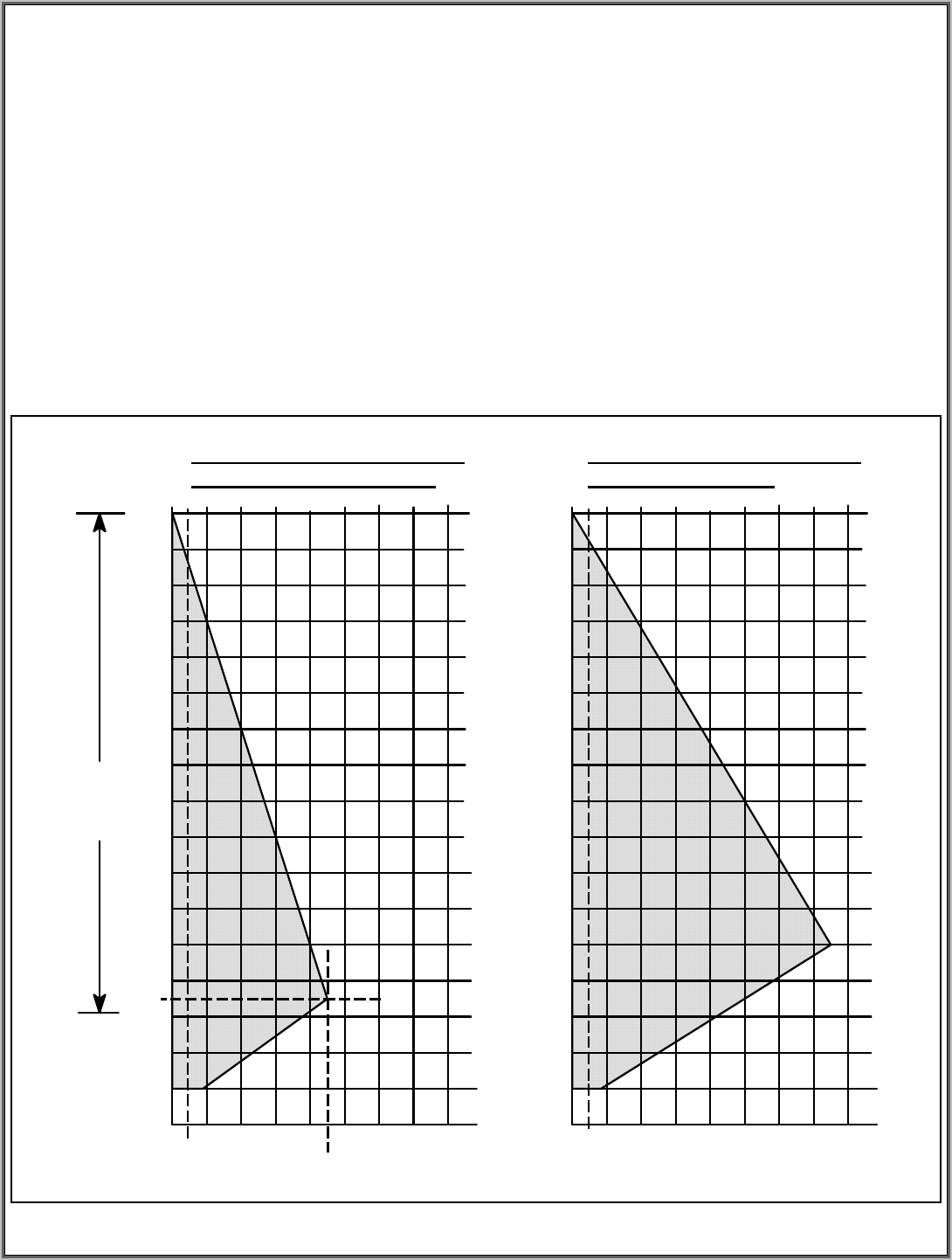
1. Determine which fuel graph chart is to be used. (Natural Gas or Propane)
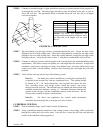
2. Determine the height from the top of the stove to the 7" elbow. Draw a horizontal line until it
intersects with the slanted graph line.
3. From the point of this intersection, draw a vertical line to the bottom of the graph.
4. Select the indicated dimension, and position the unit in accordance with the same.
Example 1: (Natural Gas Graph DV 46) If the vertical dimension from the top of the stove
is 7 feet, the horizontal run to the outer wall flange must not exceed 9 feet.
Example 2: (Propane Gas Graph DV 46) If the vertical dimension from the top of the stove
is 21 feet, the horizontal run to the outer wall flange must not exceed 8 feet.
FIGURE 18: BAYVUE DV VENT GRAPHS, MODEL DV 46
2
46810
2
4
6
8
10
12
14
16
18
20
22
24
26
28
30
12 14 16
VENTING GRAPH FOR
DV 46 NATURAL GAS
24 6810
2
4
6
8
10
12
14
16
18
20
22
24
26
28
30
32
12 14 16
VENTING GRAPH FOR
DV 46 PROPANE
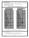
VENT TERMINATION MUST FALL IN THE GREY AREA
34
32
34
Max. Horizontal 9'
7'
Max. Vertical
Installation
34'
Min. Vertical
6'
Min. Horizontal 11"
Max. Horizontal 21" at
2' Vertical
Version 1.0h
28