


CONTROL PANEL ACCESS
HI
PIEZO
IGNITOR
LO
35.0500.00
LO
35.0500.00
IGNITOR
PIEZO
FLAME COMFORT
CONTROL
FAN SPEED
HI
OFF
LO
Country Flame
VALVE
CONTROL
Country Flame
HI
OFF
VALVE
CONTROL
LO
FAN SPEED
FLAME COMFORT
CONTROL
HI
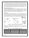
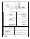
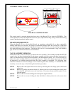
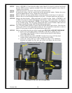
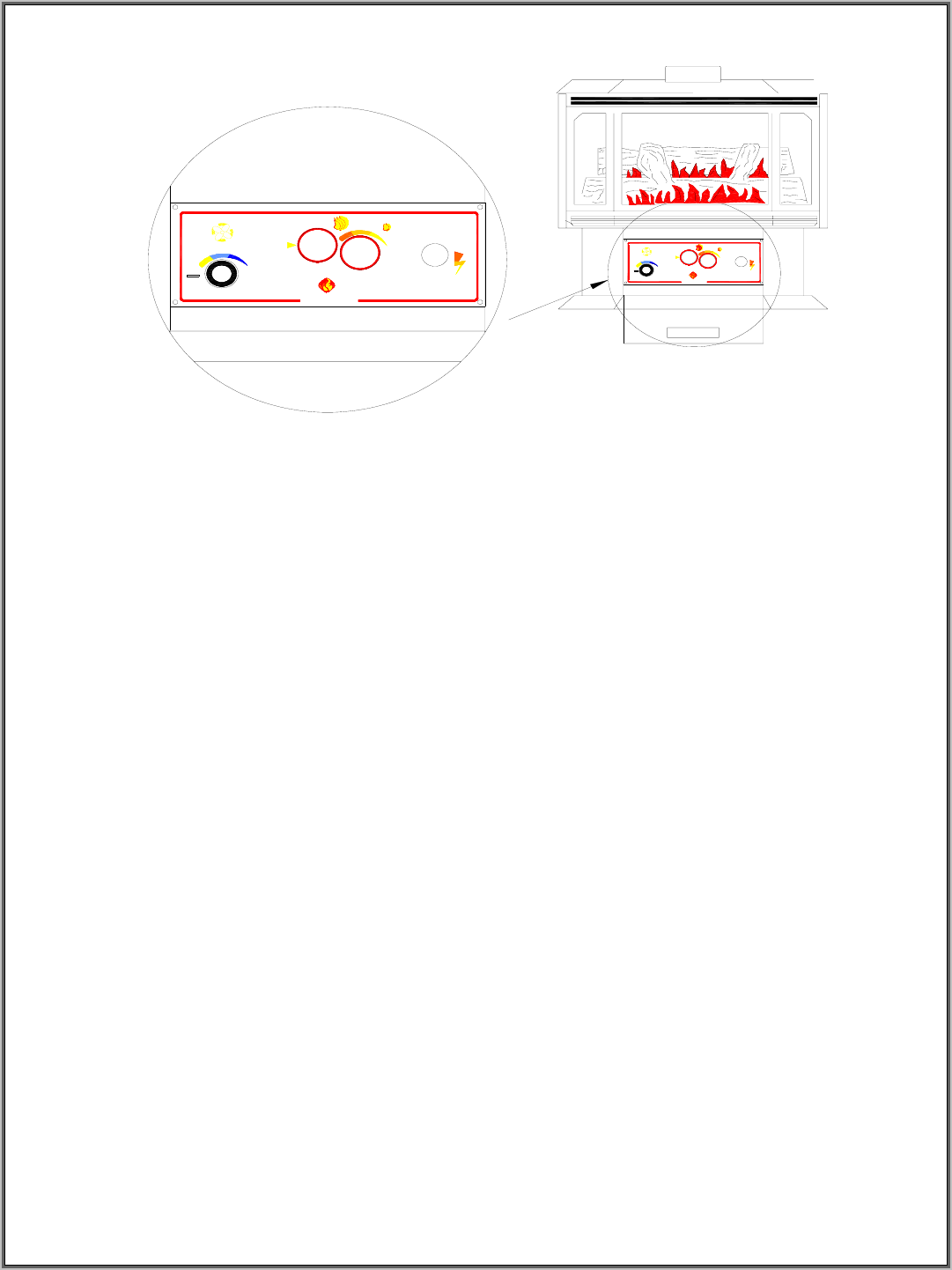
FIGURE 6: CONTROL PANEL
The control panel is accessed through the front door of the Bayvue DV as shown in FIGURE 6. The
control panel has controls that adjust the blower fan speed, adjusts the burning setting, includes the burning
control, and the piezoelectric igniter control.
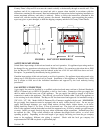
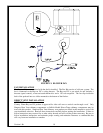
HEARTH REQUIREMENTS
When the Bayvue DV is to be installed directly on carpeting, combustible tile or other combustible
material other than wood flooring, the carpet or combustible material must be covered first. Other than
wood flooring, the floor must be covered with metal, non-combustible tile or wood paneling extending the
full width and depth of the appliance. The Bayvue DV can sit on a raised hearth as long as all chimney
pipe and all stove minimum clearances are maintained.
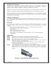
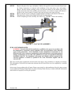
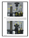
VALVE ASSEMBLY REMOVAL
From time to time, it may be necessary to remove the valve assembly. This assembly includes the SIT 820
control valve, the base mounting plate for the burner assembly, the pilot system, the three burner spud (a
spud is a removable cap or plug) orifice assemblies, and miscellaneous tubing. If it is ever necessary to
remove the valve assembly, take care not to damage any parts. Further, this system, once removed, should
be inspected by a certified professional before the valve assembly is reinstalled. The following steps
should be followed to ensure no damage occurs in removing the valve assembly. To reinstall the valve
assembly, reverse the steps as listed during the installation procedure.
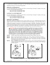
STEP 1 Remove the control panel front access door by removing the screw hinge pins at the bottom
of the door.
STEP 2 Remove by pulling the rheostat knob off. Remove the four screws holding the control panel
front bezel in place and remove the bezel plate. Disconnect the piezoelectric igniter’s wire
from the igniter.
STEP 3 Remove the four screws holding the control panel support brackets.
Version 1.0h
12
STEP 4 Remove the two screws holding the heat shield that is directly above the valve access door
area.