


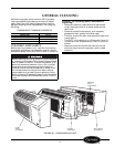
52C,P
SERIES
6
■
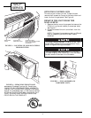
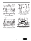
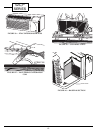
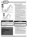
DETACH THE CONDENSER ORIFICE FROM THE
CONDENSER COIL
1. Remove top half of condenser orifice.
a. Unscrew the top half of the condenser orifice by
backing off the 4 captive screws. See Figure 13.
b. Using a flat head screwdriver, gently pry the
top half of the orifice from the tube sheets. See
Figure 14.
c. Remove top of condenser orifice. See Figure 15.
2. Remove bottom half of condenser orifice.
a. Using a flat head screwdriver, gently pry the
bottom half of the orifice from the tube sheets.
See Figure 14.
b. Remove 2 outdoor coil tube sheet screws using a
Phillips head screwdriver. See Figure 16.
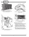
c. Carefully lift condenser up and away from con-
denser fan. Rest condenser on basepan. See
Figure 17.
d. Using Needle Nose Pliers remove condenser fan
hub clamp. See Figure 18.
e. Pull condenser fan off fan motor shaft.
f. Remove bottom half of condenser orifice.
3. Reassemble by reversing steps above.
■
REMOVE THE AIR DISCHARGE GRILLE
1. Remove the front panel from the unit, reference
Remove Front Panel section.
2. Flip the front panel over to the backside. Remove
the 2 screws on each end of the air discharge grille
and remove grille. See Figure 19.
The grille can be positioned to direct the
discharge air up or out by simply rotating
the grille 180 degrees.
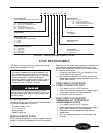
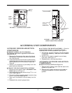
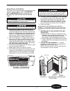
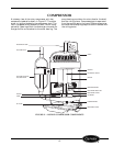
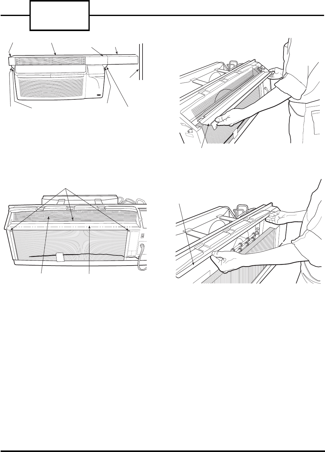
END CAP
LEFT
BRACKET
BRACKET
SCREWS
PLENUM LATERAL DUCT
EXTENSION
WALL
TOP
SCREWS (2)
BRACKET
SCREWS
RIGHT
BRACKET
ATTACHMENT
SCREWS
DISCHARGE
SCREEN
DISCHARGE
DECK
DISCHARGE DECK
HEATER PLATE
ASSEMBLY
FIGURE 8 — PTAC UNIT WITH LATERAL
DUCT ACCESSORY INSTALLED
FIGURE 9 — LOCATION OF ATTACHMENT
SCREWS ON DISCHARGE DECK OF UNIT
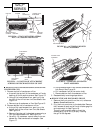
FIGURE 10 — ACCESSING HEATER
PLATE ASSEMBLY
FIGURE 11 — REMOVAL OF HEATER
PLATE ASSEMBLY