


52C,P
SERIES
20
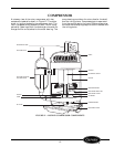
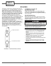
OPERATING CONTROLS
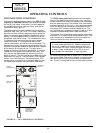
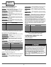
UNIT-MOUNTED CONTROLS
The controls and components used in the 52C,P cool-
ing only or heat/cool units are as follows: the selec-
tor switch, the indoor thermostat, the dual capacitor,
the temperature limiter, the vent lever, and the fan
cycle switch. See Figure 37.
The selector switch is used to determine the mode of
operation: heat, cool, fan, or off. The indoor thermostat
controls the room ambient temperature and cycles the
heater or the compressor based on the selector switch
setting. The dual capacitor aids in the start-up of the
compressor and the fan motor. The temperature limiter
is integrated into the control box top cover located
under front panel. It is a mechanical device that
restricts the amount of rotation of the thermostat. The
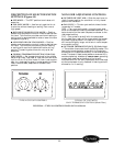
temperature limiter device may be adjusted by moving
the plastic temperature selector tabs to another temper-
ature location on the control box. The vent lever is
located on the front left side of the chassis. It is a slide
mechanism that opens and closes the vent door. The
vent control may be accessed by removing the front
panel of the unit. The fan cycle switch is used to provide
2 options of fan control. The first option, CON, causes
the fan to run continuously. The second option, CYC,
causes the fan to cycle on with the compressor or elec-
tric heater and off when the thermostat is satisfied.
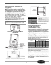
The 52C,P heat pump unit contains all the compo-
nents of the heat/cool and cooling only unit, and the
following additional ones: the outdoor frost thermostat
and the reversing valve. The outdoor frost thermostat
prevents operation of the unit in the heat pump mode
when the outdoor coil temperature drops below 20 F,
or at about 35 F outdoor ambient temperature. The
unit automatically engages the electric heat strip and
disables the compressor under these conditions.
The outdoor frost thermostat has a manual override to
place the unit in electric heat mode operation only. The
override switch is located behind the front panel on
the front side of the unit control box door.
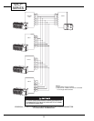
The reversing valve allows for operation in reverse cycle
heat pump mode. The valve is located in the piping sys-
tem and is controlled by the reversing valve solenoid
coil. The coil is energized only during the heating mode.
IMPORTANT: Placing the override switch to elec-
tric heat mode operation will disable the compres-
sor for ALL heating or cooling operations (for all
units except RC units). Placing the override switch
to electric heat mode operation on RC units will
only disable the compressor in heating mode.
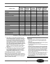
TEMPERATURE
LIMITER
FAN CYCLE
SWITCH
OUTDOOR FROST
THERMOSTAT
(HEAT PUMP
UNITS ONLY)
80
85
90
60
65
70
75
CON
CYC
SELECT0R
SWITCH
INDOOR
THERMOSTAT
FIGURE 37 — 52C,P OPERATING CONTROLS