


5
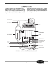
ACCESSING UNIT COMPONENTS
ACCESSING INDOOR-AIR SECTION
COMPONENTS
■
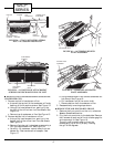
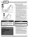
REMOVE LATERAL DUCT EXTENSION
ACCESSORY FOR UNITS EQUIPPED WITH THE
LATERAL DUCT
1. Remove the 2 top screws that secure the lateral
duct plenum to the top of the lateral duct exten-
sion. See Figure 8.
2. Locate and remove the 2 bottom bracket screws
(located opposite extension duct) that secure the
lateral duct plenum to the bracket flange. See
Figure 8.
3. Carefully lift the plenum up and away from front
panel and duct extension.
■
REMOVE THE DISCHARGE DECK ASSEMBLY
1. Remove the front panel. Refer to Remove Front
Panel section and Figure 4.
2. Remove discharge screen screw using a
5
/
16
-in. nut
driver. See Figure 9.
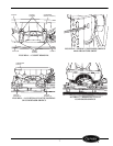
3. Remove the discharge deck assembly screws using
a
5
/
16
-in. nut driver. See Figure 9.
4. Gently pull the deck/grille up and away from the
unit.
5. Reassemble by reversing steps above.
■
ACCESSING THE HEATER ASSEMBLY
— Once the
discharge deck assembly is removed, the Heater
Assembly should now be accessible. See Figure 10.
1. Using pliers, carefully remove all wires connected
to the heater assembly. Label each wire for ease of
re-assembly.
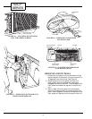
2. Gently pull the heater assembly up and away
from scroll. See Figure 11.
3. Reassemble by reversing steps above.
ACCESSING OUTDOOR-AIR SECTION
COMPONENTS
■
REMOVE THE GUSSETS (See Figure 12)
1. Remove the 2 screws on each side that secure the
gussets to the partition.
2. Remove the 2 screws that secure the gussets to
the plastic condenser orifice and remove the
gussets.
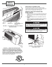
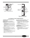
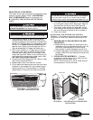
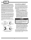
POWER
CORD
ACCESS
COVER
POWER
CORD
CONTROL
BOX
SCREWS
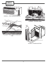
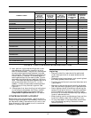
GE WALL
SLEEVE
HOLES
AMANA, TRANE
(SLOTTED
HOLES) WALL
SLEEVE HOLES
VARIOUS ATTACHMENT
HOLE LOCATIONS
CARRIER, BRYANT
WALL SLEEVE
HOLES
FIGURE 6 — CONTROL BOX COVER
FIGURE 7 — PTAC UNIT TO WALL
SLEEVE MOUNTING SCREWS