


41
WIRING DIAGRAMS
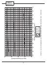
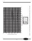
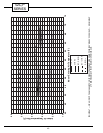
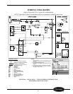
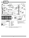
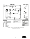
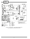
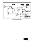
Refer to Figures 68-72 for Typical Wiring Schematics.
NOTE: Figures 68-72 should not be substituted for the schematic located on control box.
FIGURE 68 — 52CQ & 52PQ — TYPICAL WIRING SCHEMATIC FOR
STANDARD HEAT PUMP UNITS
COMPONENT LEGEND
Component Connection (Marked)
Component Connection (Unmarked)
Accessory or Optional Wiring
To Indicate Common Potential Only
Not To Represent Wire
CAP —
Capacitor
COMP —
Compressor
FM —
Fan Motor
FCS —
Fan Cycle Switch
HTR —
Heater
IT —
Indoor Thermostat
NEC —
National Electrical Code
OFT —
Outdoor Frost Thermostat
OL —
Overload
PLS —
Primary Limit Switch
RVS —
Reversing Valve Solenoid
SLS —
Secondary Limit Switch
ST —
Start Thermistor
SW —
Switch
NOTES:
1. Recommended for use on grounded power sup-
ply only.
2. Compressor and fan motor thermally protected.
3. Use copper conductors only.
4. All wiring must conform with NEC and local
codes.
5. Dashed lines indicate components when used.
6. OFT determines whether to bring on compres-
sor heat or electric heat.