


19
■
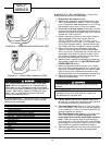
TOOLS NEEDED
— The following list includes rec-
ommended tools and devices for working on the heater
section of 52C,P units.
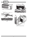
Perform the following steps to remove the Heater
Assembly.
1. DISCONNECT ALL POWER TO UNIT.
2. Remove heater by following instructions in
ACCESSING UNIT COMPONENTS section.
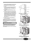
After the heater is removed, examine the heater
as follows to determine if it is operational:
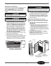
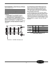
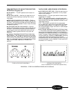
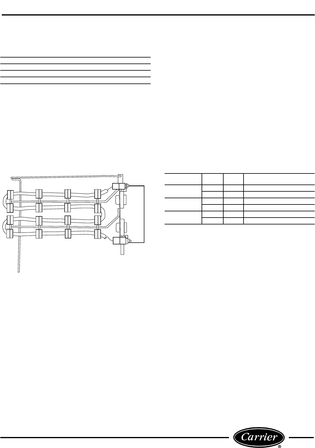
Perform a visual inspection. The heater coil should be
free of breaks. If there are any breaks in the coil,
replacement of the heater assembly is necessary. See
Figure 35.
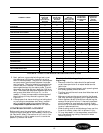
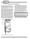
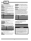
Coil resistance must also be checked to verify the
heater is operating correctly. The resistance of the
heater coils must meet approximate levels for the
heater to perform at its optimum efficiency. See
Figure 36 for approximate resistance for heaters at
75 F. Before checking the heater coil resistance, be
sure all power to unit is off.
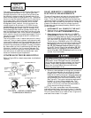
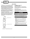
To check resistance, set the volt-ohmmeter selector
switch to the lowest ohms value. Next connect the volt-
ohmmeter leads to each side of the heater coil at the
studs that hold the limit switches in place. Incorrect
readings can be obtained if the wires are not removed
from the limit switches on the heater assembly. If the
resistive reading is infinite or zero, the heater is failed
and replacement is necessary. Reinstall the heater
assembly.
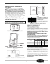
FIGURE 36 — ACCEPTABLE HEATER
RESISTANCE VALUES
Phillips Head Screw Driver
Needle Nose Pliers
Volt-ohmmeter
Nut Driver
5
/
16
-in.
HEATER SIZE WATTS VOLTS
ACCEPTABLE RESISTANCE
(Ohms)
2.3 kW
2300 230 20-23
2300 265 28-31
3.4 kW
3400 230 13-16
3400 265 19-21
5.0 kW
5000 230 9-11
5000 265 13-15
FIGURE 35 — HEATER COIL (Removed)