


29
FAN MOTOR
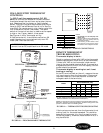
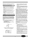
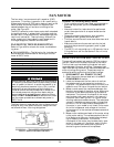
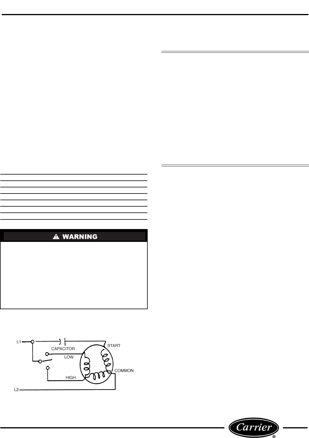
The fan motor is a permanent split capacitor (PSC)
type motor. This motor is common in air-conditioning
system applications. A PSC motor does not require the
use of a relay and always has a run capacitor con-
nected between the run and start windings of the
motor. See Figure 55.
The 52C,P series fan motor has a motor shaft extended
through both ends. It powers both the indoor and the
outdoor fans. It has permanently sealed bearings that
require no lubrication. There are many different fan
motor models, but they typically are 2-speed and in
2 voltage categories, 208/230 and 265 volts.
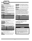
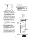
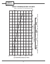
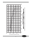
FAN MOTOR TROUBLESHOOTING
Refer to Figure 56 for a basic fan motor troubleshoot-
ing chart.
■
TOOLS NEEDED
— The following list includes rec-
ommended tools and devices for working on the fan
motor of 52C,P units
.
The Manufacturer reserves the right to discontinue, or
change at any time, specifications or designs without
notice and without incurring obligations.
BASIC FAN MOTOR ELECTRICAL TESTS
There are 2 basic electrical tests for PSC fan motors
that will determine the electrical state of the motor.
The first test requires checking the electrical resis-
tance between the motor windings. The second test
requires checking the electrical resistance between the
motor windings and ground. These tests may be
accomplished by performing the following steps:
1. DISCONNECT ALL POWER TO UNIT.
2. Open the control box as detailed in the UNIT
DISASSEMBLY section.
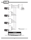
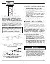
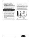
3. Label and disconnect the fan motor wires from
the selector switch and capacitor as shown in
Figure 54. Two-speed motors have 2 wires on the
capacitor and 2 wires on the push button switch.
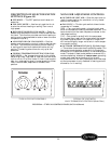
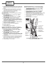
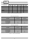
4. Measure and record the resistance between the
black wire and each of the other wires. Make sure
the motor is cool before attempting to measure
resistance. The internal thermostat of the motor
may be electrically open and will not close until
the motor cools. See Figure 57 for typical motor
winding resistance measurements. The resistance
values in the table are approximate. Values that
are within 10% of those listed are acceptable. If
the motor in your model is not listed, find a motor
of similar horsepower and voltage on the chart
and compare it to the resistance measurements of
your motor.
5. Measure the resistance of each of the motor wires
to the motor casing. The resistance should be infi-
nite. Make sure the motor is cool before attempt-
ing to measure resistance. The internal
thermostat of the motor may be electrically open
and will not close until the motor cools. A motor
that has measurable resistance to ground is
shorted to ground and must be replaced.
Gloves
Safety Glasses
Regular and Phillips Head Screw Drivers
Small Adjustable Wrench
Channel Lock Pliers
Volt-ohmmeter
5
/
16
-in. Nut Driver
Before cleaning, servicing, performing maintenance
or removing the chassis from the wall sleeve, discon-
nect all power to the unit to avoid the possibility of
electrical shock and personal injury. Only trained
and qualified service personnel should perform
installation and service procedures on these units.
Untrained personnel may perform basic mainte-
nance tasks such as cleaning and replacing filters.
Refer to UNIT DISASSEMBLY section of this man-
ual for proper procedures to disconnect power to
52C,P units.
Consider the following safety issues:
• Prior to performing any service or maintenance on
electrical equipment you must Disconnect All
Power.
• New and unfamiliar tasks should be performed
under the supervision of an experienced service
technician.
• Personal protective equipment, such as safety
glasses and work gloves, should be worn.
• The floor around the work area should be clean and
free of debris.
• Make sure tools are the correct tools for the job,
and that they are working properly and in good
condition.
• The 52C,P unit may weigh up to 150 pounds. Use a
lifting device or ask for assistance if the unit must
be moved.
FIGURE 55 — TWO-SPEED, PERMANENT
SPLIT CAPACITOR MOTOR (PSC)