


31
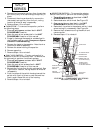
FAN MOTOR REPLACEMENT
1. DISCONNECT ALL POWER TO UNIT.
2. Remove the unit from the sleeve as detailed in the
UNIT DISASSEMBLY section and place the unit
on a large flat surface.
3. Remove the discharge deck and grille as detailed
in Remove the Discharge Deck Assembly section.
4. Remove heater plate assembly as detailed in
Accessing the Heater Assembly section. The
blower wheel should now be accessible.
5. Using adjustable pliers, carefully remove the
5
/
32
-in. Allen clip that secures the blower wheel to
the fan shaft. Remove the blower wheel.
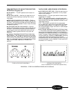
6. Open the Control box as described in the UNIT
DISASSEMBLY section, Open the Control
Box. Disconnect the fan motor wires from the
rotary switch and capacitor. All units are
equipped with two-speed motors, which have
2 wires on the capacitor and 2 wires on the rotary
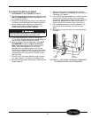
switch. Refer to the unit wiring schematic which
is attached to the front panel of the control box.
See Figure 58.
7. Carefully pull fan motor leads through the parti-
tion hole, located in the back of the control box.
8. Remove the top gussets, as detailed in Remove the
Gussets section.
9. Remove the top half of the condenser orifice as
detailed in Detach the Condenser Orifice From the
Condenser Coil section.
10. Using a Phillips head screwdriver, remove the fan
motor shield. The fan motor mounting screws
should now be accessible. Remove the 3 mounting
screws that secure the fan motor to the motor
mount and remove the fan motor from the unit.
11. Using needle nose pliers, remove condenser fan
hub clamp. Slide condenser fan off fan motor
shaft.
12. Re-install the new fan motor by reversing Steps 1
through 11.
Safety glasses should be worn to protect eyes in the
event the spring clip breaks free from pliers.
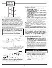
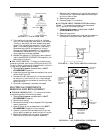
WIRING
SCHEMATIC
POWER
CORD
FIGURE 58 — LOCATION OF WIRING SCHEMATIC
ON FRONT PANEL OF CONTROL BOX