


52C,P
SERIES
24
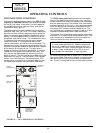
SEQUENCE OF OPERATION
■
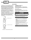
HEAT/COOL UNITS (Figure 45)
Fan Mode
— With the selector switch set to FAN con-
tacts L1 to HI and FCS1 to LS are made.
Cooling (Low)
— With the selector switch set to low
speed cooling contacts FCS2 to LO, COMP to FCS1,
and COMP to IT3 are made.
Cooling (High)
— With the selector switch set to high
speed cool contacts FCS2 to HI, COMP to FCS1, and
COMP to IT3 are made.
Heating (Low)
— With the selector switch set to low
speed heat contacts FCS2 to LO, IT1 to LS, L2 to HTR,
and FCS1 to LS are made.
Heating (High) —
With the selector switch set to high
speed heat contacts FCS2 to HI, IT1 to LS, L2 to HTR,
and FCS1 to LS are made.
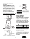
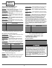
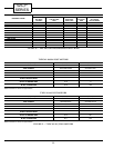
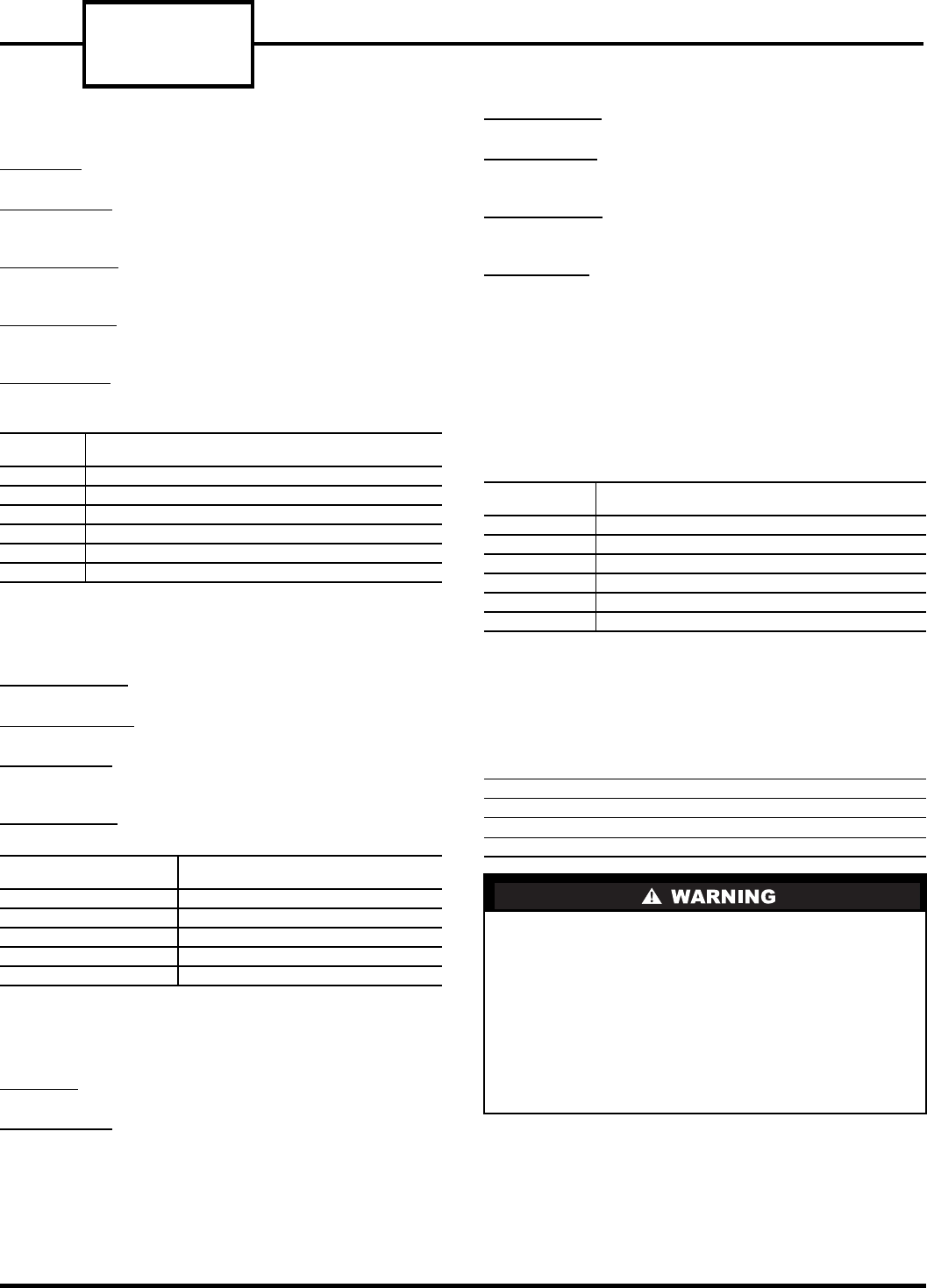
FIGURE 45 — SELECTOR SWITCH CONTACTS,
ALL 52CE, PE ELECTRIC HEAT/COOL UNITS
■
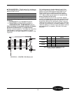
COOLING ONLY UNITS (Figure 46)
Fan Mode (Low)
—
With the selector switch set to FAN
contact L1 to LO is made.
Fan Mode (High)
—
With the selector switch set to
FAN contact L1 to HI is made.
Cooling (Low)
—
With the selector switch set to low
speed cooling contacts FCS to LO and L1 to IT3 are
made.
Cooling (High)
—
With the selector switch set to high
speed cool contacts FCS to HI, L1 to IT3 are made.
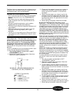
FIGURE 46 — SELECTOR SWITCH CONTACTS,
ALL 52CE, PE COOLING ONLY UNITS
■
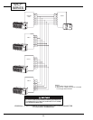
HEAT PUMP UNITS (Figure 47)
Fan Mode
—
With the selector switch set to fan contact
L1 to HI is made.
Cooling (Low)
—
With the selector switch set to low
cool contacts L1 to IT3 and FCS to LO are made.
Cooling (High)
—
With the selector switch set to high
cool, contacts L1 to IT3 and FCS to HI are made.
Heating (Low)
—
With the selector switch set to low
heat contacts L1 to IT1, FCS to LO and L2 to HTR are
made.
Heating (High)
—
With the selector switch set to high
heat contacts L1 to IT1, FCS to HI, and L2 to HTR are
made.
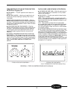
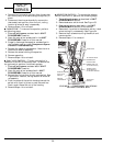
Defrost Cycle
—
When heat pump unit is operating in
reverse cycle, the outdoor coil may begin to frost. As
frost accumulates on the outdoor coil the unit may
switch into defrost mode. The defrost mode is acti-
vated when the outdoor frost thermostat sensor
detects a temperature below 20 F on the coil. At this
point, the thermostat deenergizes the compressor and
activates the electric heat. The unit will remain in
electric heat mode until the outdoor thermostat senses
35 F coil temperature. The defrost mode is a passive
operation and may take some time before the coil
defrosts.
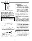
FIGURE 47 — SELECTOR SWITCH CONTACT,
ALL 52CQ, PQ HEAT PUMP UNITS
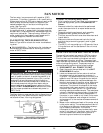
COMPONENT OPERATION AND
TROUBLESHOOTING
■
TOOLS NEEDED
SWITCH
POSITION
CONTACTS MADE
OFF
NONE
FAN
L1 TO HI, FCS1 TO LS
LO HEAT
FCS2 TO LO, IT1 TO LS, L2 TO HTR, FCS1 TO LS
HI HEAT
FCS2 TO HI, IT1 TO LS, L2 TO HTR, FCS1 TO LS
LO COOL
FCS2 TO LO, COMP TO FCS1, COMP TO IT3
HI COOL
FCS2 TO HI, COMP TO FCS1, COMP TO IT3
SWITCH
POSITION
CONTACTS MADE
OFF
NONE
FAN LO
L1 TO LO
FAN HI
L1 TO HI
LO COOL
L1 TO IT3, FCS TO LO
HI COOL
L1 TO IT3, FCS TO HI
SWITCH
POSITION
CONTACTS MADE
OFF
NONE
FAN
L1 TO HI
LO HEAT
L1 TO IT1, FCS TO LO, L2 TO HTR
HI HEAT
L1 TO IT1, FCS TO HI, L2 TO HTR
LO COOL
L1 TO IT3, FCS TO LO
HI COOL
L1 TO IT3, FCS TO HI
Volt-Ohmmeter
Flat and Phillips Screw Drivers
5
/
16
-in. Nut Driver
Side Cutting Pliers
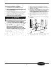
Before cleaning, servicing, performing maintenance
or removing the chassis from the wall sleeve, discon-
nect all power to the unit to avoid the possibility of
electrical shock and personal injury. Only trained
and qualified service personnel should perform
installation and service procedures on these units.
Untrained personnel may perform basic mainte-
nance tasks such as cleaning and replacing filters.
Refer to UNIT DISASSEMBLY section of this man-
ual for proper procedures to disconnect power to
52C,P units.