


52C,P
SERIES
26
■
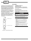
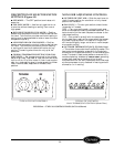
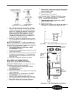
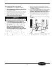
OUTDOOR FROST THERMOSTAT (Heat Pump
Units) (Figure 50A and 50B) —
The Outdoor Frost
Thermostat (OFT) is a thermostat that uses a single-
pole switch with a manual override selector. The ther-
mostat switches between electric heat and compressor
operation when the temperature of the outdoor coil
falls below 20 F or rises above 35 F. Switching the
override selector to electric heat disables the reverse
cycle operation of the thermostat and is manually
switched to electric heat operation.
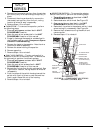
To verify the OFT is operational, a continuity test may
be performed as follows:
1. Turn off unit power as described in UNIT
DISASSEMBLY section.
2. Remove the leads from the OFT. Note their loca-
tions to ease re-assembly.
3. Connect the continuity tester to the switch termi-
nals marked 1 and 2.
4. Rotate the override switch to the electric heat set-
ting and verify that there is continuity between
terminals 1 and 2.
5. To check the other contacts, move the lead on ter-
minal 1 to terminal 3. Rotate the override switch
to the heat pump setting. There should now be
continuity between terminals 2 and 3.
6. Once the test is complete, reconnect the leads.
■
CAPACITOR —
The 52C,P units use a dual
capacitor. One part of the capacitor is used with the
fan motor. The other part of the capacitor is used by
the compressor.
Run circuits on single-phase compressor motors use
capacitors which dramatically affect the motor opera-
tion. Run capacitors are connected to the motor circuit
at all times.
To evaluate the capacitor, perform a visual check first.
A shorted capacitor may give a visual indication of its
failure. For example, the pop-out hole at the top of a
start capacitor may bulge or blow out. A run capacitor
may bulge or leak. In these instances, the capacitor
must be replaced with one recommended by the manu-
facturer. If there are no visual signs of capacitor fail-
ure, testing of the capacitor resistance may be done
with a volt-ohmmeter as detailed below:
1. Turn off unit power as described in UNIT
DISASSEMBLY section but do not unplug the
service cord; it will supply ground connection for
the unit chassis. Check to ensure power is off
and LOCKED OUT.
2. Connect one lead of a 20,000 ohm, 2-watt resistor
to the center group of terminals on the dual capac-
itor. Attach the other lead from the resistor to an
unpainted metal section of the unit chassis. This
allows that section of the dual capacitor to dis-
charge. Repeat this process between the other
group of terminals.
3. Locate and disconnect the wires from the start
and/or run capacitor to isolate them from the
remainder of the circuit. Refer to the unit wiring
diagram if you need assistance locating wires.
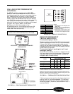
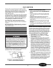
4. Perform capacitor test. Set up the volt-ohmmeter
to measure resistance by connecting terminals C
to FAN and C to HERM on the meter. See
Figure 51.
IMPORTANT: Placing the override switch to elec-
tric heat mode operation will disable the compres-
sor for ALL heating or cooling operations (for all
units except RC units). Placing the override switch
to electric heat mode operation on RC units will
only disable the compressor in heating mode.
Capacitors are capable of holding charge similar to a
battery and may cause an electrical shock.
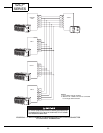
FIGURE 50A — OUTDOOR FROST THERMOSTAT
(OFT) CONTACTS, ALL 52CQ, PQ UNITS WITH
MOUNTED CONTROLS
FIGURE 50B — OUTDOOR FROST THERMOSTAT
(OFT) CONTACTS, ALL 52CQ, PQ UNITS WITH
WALL THERMOSTAT CONTROL
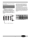
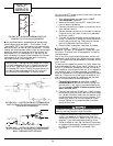
ORN
BLK
BLU
GRY
BRN
IT
2
1
3
4
6
5
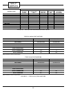
FIGURE 49 — INDOOR THERMOSTAT (IT)
CONTACTS, ALL 52CQ, PQ MODELS