


52C,P
SERIES
14
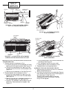
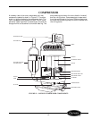
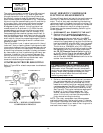
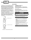
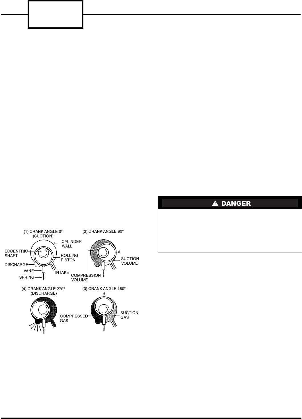
The rotary compression process (Figure 28), starts at
top dead center as shown in (1). Suction gas flows
through the suction inlet and into the cylinder area.
As the shaft rotates through 90 degrees, the rolling
piston moves to position A as shown in (2). The suction
volume is now the area defined by point A and the tip
of the vane. Gas in the remaining volume has been
compressed above suction pressure. After another
90 degrees of shaft rotation, the rolling piston has
moved to position B as shown in (3). Both the com-
pressed gas and suction gas volumes are now equal.
Another 90 degrees of shaft rotation is shown in (4).
Compressed gas has reached a pressure sufficient to
open the discharge valve, and flows from the cylinder
into the compressor shell. After another 90 degrees of
shaft rotation, the entire process begins again. Contin-
uous suction and discharge allows for a smooth com-
pression process.
The rolling piston is not in actual contact with the cyl-
inder wall, vane, or bearing faces. Hydrodynamic seal-
ing prevents leakage from the compressed gas volume
to the suction volume via these paths. Precise control
of machining tolerances, surfaces, finishes, and assem-
bly clearances is critical to achieve high efficiency per-
formance. In addition, the line contact between the
vane tip and the rolling piston requires careful selec-
tion and control of materials to provide wear resis-
tance and reliable long-term operation.
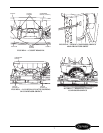
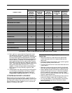
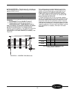
COMPRESSOR TROUBLESHOOTING
Refer to Figure 29 for a basic compressor troubleshoot-
ing chart.
BASIC HERMETIC COMPRESSOR
ELECTRICAL MEASUREMENTS
There are 2 basic electrical tests for hermetic compres-
sors that will determine the electrical state of the
motor. The first test requires checking the electrical
resistance of each of the electrical motor windings. The
second test requires checking the electrical resistance
of each of the electrical motor windings to ground.
These tests may be accomplished by performing the
following steps:
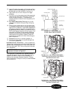
1. DISCONNECT ALL POWER TO THE UNIT.
2. Remove the unit chassis from the sleeve as
detailed in the UNIT DISASSEMBLY section.
3. Open the control box as detailed in the UNIT
DISASSEMBLY section, then locate, label, and
remove the 3 compressor wires from the following
locations: the RUN wire (BLACK) from the capac-
itor, the START wire (BLUE) from the capacitor.
The third wire, COMMON wire (YELLOW) may
be connected to one of the following locations: for
PC units the wire is on the indoor thermostat,
for CE, PE Remote Control Units the wire is
on the RC Control Board, for all other CE, PE
Units the wire is located on the rotary selector
switch. For ALL CQ, PQ Units the wire is on the
outdoor frost thermostat.
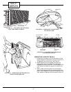
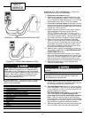
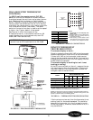
4. Perform a shorted/open windings test to measure
the resistance between the windings of the com-
pressor motor. Use a volt-ohmmeter set to the
lowest ohm reading level then read and record the
resistance between the RUN and START, START
and COMMON, and RUN and COMMON wires.
See Figure 30. The typical resistance readings will
be about 4, 3, and 1 ohms respectively. The
smaller values should add to equal the larger
value. If this is not true then the compressor is
likely shorted winding to winding.
NOTE: The rotary compressor has the compressor
overload located under the terminal cover. If the over-
load is open it can show ohm readings that are infinite.
The unit should be off for at least an hour to give this
overload time to reset if it is open.
For compressors that are known to be dam-
aged: Remove refrigerant prior to disconnecting
compressor wires. Damaged hermetic compressor
terminals may become loose and eject from the com-
pressor. Wear safety glasses and keep your face
away from the area above the terminals when
removing compressor wires.
FIGURE 28 — ROTARY COMPRESSOR
COMPRESSION PROCESS