


21
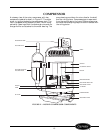
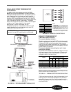
WALL-MOUNTED THERMOSTAT
CONTROLS
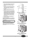
For 52C,P wall thermostat control (RC, RP)
units, all controls are located on the wall-mounted
thermostat except the vent lever and outdoor thermo-
stat. Remote control is a factory or field-installed
option. There are 3 styles of thermostats qualified for
use with 52C,P series Remote Control units. See Fig-
ures 38-40. On remote control units, the fan cycle func-
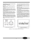
tion is located on the wall thermostat. The rocker
switch on the control box door is used to set fan speed
to high or low. Factory default is low speed.
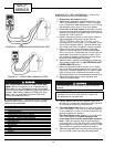
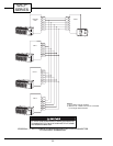
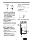
See Figures 41-43 for thermostat wiring.
A field conversion kit is available to convert an AA
model (standard unit-mounted controls) to an RC
model (wall-mounted controls).
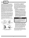
REMOTE THERMOSTAT
TROUBLESHOOTING
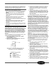
Thermostat display is blank:
Check to make sure there is 24 VAC to the thermostat
(measure across terminals R and C at the thermostat).
If there is 24 VAC at the thermostat, check connec-
tions at the thermostat terminal block. If connections
are good and there is 24 VAC with no display, the ther-
mostat should be replaced.
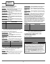
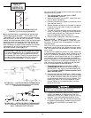
Thermostat display is working but unit is not
heating or cooling:
At the RC terminal block on the unit, measure the con-
trol inputs coming from the thermostat. (Place one of
the meter leads on C and use the other to check the
voltage at each of the terminals.)
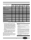
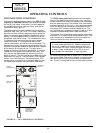
*24 VAC supplied if thermostat is in 2nd stage heating demand (large
difference between room temperature and setpoint).
NOTE: For heat pump units, the Outdoor Frost Thermostat (OFT) will
determine, based on outdoor temperature, whether to bring on the com-
pressor or electric heat in the Heating mode.
FIGURE 42 — THERMOSTAT TROUBLESHOOTING
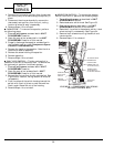
If the inputs are not correct, then the thermostat is not
making a call for the mode requested. This could be
because the thermostat is in a unit protection mode,
not set up properly, miswired, has a broken wire, or it
may have failed.
IMPORTANT: No conversion kit is available to
convert from an RC model back to an AA model.
MODE
TERMINAL
METER READINGS (VAC)
RGY W
O (For
HP Only)
Fan Only
24 24 0 0 0
Cooling
24 24 24 0 24
Heating
Heat Pump Unit
24 24 24 0/24* 0
Heat/Cool Unit
24 24 0 24 0
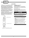
FIGURE 38 — NON-PROGRAMMABLE
THERMOSTAT
FIGURE 39 — MANUAL THERMOSTAT
FIGURE 40 — PROGRAMMABLE THERMOSTAT
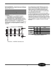
TYPICAL
WALL
THERMOSTAT
R
G
Y
W
O
C
TERMINAL
BLOCK
R
G
Y
W
O
C
FIGURE 41 — WIRING CONNECTIONS
TERMINAL DESIGNATION
R
24 VAC
G
Fan
Y
Compressor
W
Electric Heat
O
Reversing Valve
C
Common
NOTES:
1.
Use terminal “O” for heat pump con-
nection only
.
2. See table at left for terminal descriptions.
3. Common wire “C” is typically used only
for digital thermostats.
4. Power stealing is NOT allowed. There
must always be a hard common connec-
tion between unit and digital thermostat.