


27
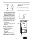
5. The reading on the meter should first indicate
zero, or a low resistance, then slowly rise toward
infinity or some high value or measurable resis-
tance. This indicates the capacitor is most likely
good. If the reading goes to zero or a low resis-
tance and stays there, the capacitor is likely
shorted and needs replacement. If the reading
immediately indicates infinity, the capacitor is
likely open and must be replaced.
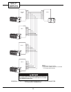
6. Replace the capacitor if failed and rewire accord-
ing to the WIRING SCHEMATICS located in the
control box of the unit.
■
FAN CYCLE SWITCH —
The fan cycle switch has
2 operating modes, continuous (CON) and cycle (CYC).
To verify the fan cycle switch is operational, a continu-
ity test may be performed as follows:
1. Turn off unit power as described in UNIT
DISASSEMBLY section.
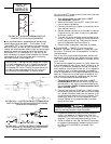
2. Label and remove the leads connected to fan cycle
switch. See Figure 52.
3. Connect the volt-ohmmeter for 1X ohms and check
for continuity from terminal 2 to 1 then change
the switch position and check for continuity from
terminal 2 to 3.
4. Once test is complete, reconnect the leads.
ELECTRICAL COMPONENTS
REMOVAL AND REPLACEMENT
■
INDOOR THERMOSTAT
— To remove the indoor
thermostat, perform the following steps:
1. Turn off unit power as described in UNIT
DISASSEMBLY section.
2. Remove front panel.
3. Remove thermostat knob to expose 2 Phillips head
mounting screws.
4. Open the control box as described in the UNIT
DISASSEMBLY section of this manual.
5. Carefully remove the thermostat bulb from the
clip by gently pressing it down and out of the clip.
6. Remove the leads from the indoor thermostat.
Note the wire locations to ease re-assembly.
7. Remove the 2 screws mounting the thermostat to
the control box. Route thermostat bulb and capil-
lary out of control box.
8. Remove thermostat.
9. Reverse Steps 1-8 to reinstall.
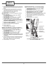
■
OUTDOOR FROST THERMOSTAT (Heat Pump
Units)
— To remove the outdoor frost thermostat
(OFT), perform the following steps:
1. Turn off unit power as described in UNIT
DISASSEMBLY section.
2. Remove front panel.
3. Remove the 2 screws mounting the thermostat to
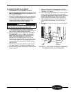
the bottom of the control box. See Figure 53.
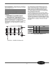
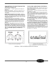
FIGURE 51 — CAPACITOR TEST
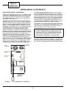
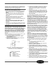
TEMPERATURE
CONTROL
STANDOFF
PINS
FAN CYCLE
SWITCH
OUTDOOR FROST
THERMOSTAT
(HEAT PUMP
UNITS ONLY)
80
85
90
60
65
70
75
CON
CYC
SELECT0R
SWITCH
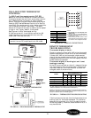
OFT
MOUNTING
SCREWS
FIGURE 53 — 52C,P OPERATING CONTROLS
FIGURE 52 — FAN CYCLE SWITCH (3 Terminal)