


52C,P
SERIES
42
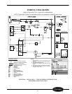
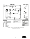
TYPICAL THERMOSTAT INTERFACE
1. If ‘W’ is ON, then ‘FR’ is forced ON (regardless of ‘G’) & ‘CR’ is forced OFF.
2. If ‘Y’ is ON, then ‘FR’ is forced ON (regardless of ‘G’).
3. If IFT (indoor coil) is < 35° F, then ‘CR’ is forced OFF until IFT is > 39° F.
T’STAT OUTPUT: RC CONTROLER OUTPUT: UNIT OPERATION:
‘G’ — 24 VAC
‘G’ — 0 VAC
‘FR’ — LINE VAC
‘FR’ — 0 VAC
FAN
‘Y’ — 24 VAC
‘O’ — 0 VAC
‘HR1 & HR2’ — LINE VAC
‘RVR’ — LINE VAC
HEATING
‘W’ — 24 VAC ‘HR1 & HR2’ — LINE VAC HEATING
‘Y’ — 24 VAC
‘O’ — 24 VAC
‘CR’ — LINE VAC
‘RVR’ — 0 VAC
COOLING
‘R’ — 24 VAC
‘C’ — COMMON
‘R’ — 24 VAC OUTPUT
‘C’ — COMMON
POWER TO WALL
THERMOSTAT
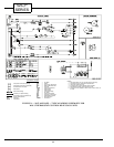
NOTES:
1. Recommended for use on grounded power supply only.
2. Compressor and fan motor thermally protected.
3. Use copper conductors only.
4. All wiring must conform with NEC and local codes.
5. Dashed lines indicate components when used.
6. Field control wire suitable for NEC class 2 control circuit, at
24 volts.
7. OFT determines whether to bring on compressor heat or
electric heat.
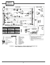
FIGURE 69 — 52CQ AND 52 PQ — TYPICAL WIRING SCHEMATIC FOR
WALL THERMOSTAT HEAT PUMP UNITS
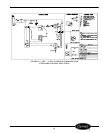
Component Connection (Marked)
Component Connection (Unmarked)
Terminal Board Connection
Field Splice
Field Control Wiring
Accessory or Optional Wiring
To Indicate Common Potential Only
Not To Represent Wire
CAP —
Capacitor
COMP —
Compressor
FM —
Fan Motor
COMPONENT LEGEND
HTR —
Heater
IFT —
Indoor Frost Thermostat
NEC —
National Electrical Code
OFT —
Outdoor Frost Thermostat
OL —
Overload
PCBD —
Printed Circuit Board
HR1 —
Heater Relay
HR2 —
Heater Relay
CR —
Compressor Relay
FR —
Fan Relay
RVR —
Reversing Valve Relay
PLS —
Primary Limit Switch
RVS —
Reversing Valve Solenoid
SLS —
Secondary Limit Switch
SSS —
Speed Selector Switch
ST —
Start Thermistor
TRANS —
Transformer