


25
The Manufacturer reserves the right to discontinue, or
change at any time, specifications or designs without
notice and without incurring obligations.
■
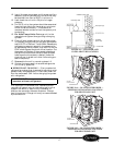
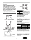
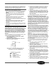
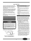
INDOOR THERMOSTAT (Heat/Cool and Cool Only
Units) (Figure 48) —
The thermostat maintains the
selected temperature by cycling the compressor on and
off during cooling operation and the electric heater
during heating operation. The thermostat DOES
NOT switch from heating to cooling, or cooling
to heating. If the switch is in the CYCLE position,
then the fan will be cycled off when the thermostat
satisfies.
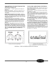
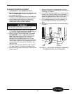
To verify the operation of the thermostat switch, a con-
tinuity test may be performed as follows:
1. Turn off unit power as described in UNIT
DISASSEMBLY section.
2. Remove wire leads from thermostat. Note their
locations to ease re-assembly.
3. Place one of the leads of the continuity tester on
the terminal marked 2, and the other lead on
either the terminal marked 1 or the terminal
marked 3.
4. Adjust the thermostat up or down to verify the
contacts of the switch open and close. When veri-
fying continuity of a closed switch, the ohm read-
ing should be 0 ohms. An open switch will show
OL on the meter.
5. When testing is complete, reconnect the leads.
■
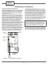
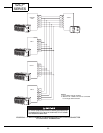
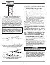
INDOOR THERMOSTAT (Heat Pump Units)
(Figure 49) —
The heat pump indoor thermostat uses a
two-stage switch for the heating mode. The first stage
engages the compressor and reversing valve, and the
unit operates in normal heat pump mode. The indoor
thermostat maintains the selected temperature by
cycling the compressor on and off in cooling mode. In
the heating mode, the indoor thermostat will cycle the
compressor or the heater, depending on the difference
between the actual room temperature and the thermo-
stat temperature setting.
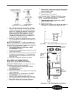
When the room temperature is more than 4 F cooler
than the indoor thermostat setting, the second heating
stage of the indoor thermostat engages the electric
heat strip. This design feature allows the user to rap-
idly warm the room with the electric heat strip by
turning the thermostat to its highest setting. When
room temperatures approach the desired temperature,
the user may adjust the thermostat to a personal
comfort setting, which allows for normal heat pump
operation.
NOTE: For outdoor coil temperatures below approxi-
mately 20 F, the outdoor frost thermostat prevents
heat pump mode operation and immediately engages
the electric heat strip upon a call for heating. The elec-
tric heat strip is NEVER energized at the same time
as the compressor.
To verify operation of the heat pump indoor thermo-
stat switch, a continuity test may be performed as
follows:
1. Turn off unit power as described in UNIT
DISASSEMBLY section.
2. Remove wire leads from thermostat. Note their
locations to ease re-assembly.
3. To test stage A, place one lead of the continuity
tester on the terminal marked 2, and the other
lead on either the terminal marked 1 or the termi-
nal marked 3.
4. Adjust the thermostat up or down to verify the
contacts of the switch open and close. When veri-
fying continuity of the closed switch, the reading
on the meter should be 0 ohms. An open switch
will show OL on the meter.
5. To test stage B contacts, place one lead of the con-
tinuity tester on contact 5 and the other lead on
either contact 4 or contact 6.
6. Adjust the thermostat up or down to verify the
contacts of the switch open and close as in Step 4.
7. When testing is complete, reconnect the leads.
Consider the following safety issues:
• Prior to performing any service or maintenance on
electrical equipment you must Disconnect All
Power.
• New and unfamiliar tasks should be performed
under the supervision of an experienced service
technician.
• Personal protective equipment, such as safety
glasses and work gloves, should be worn.
• The floor around the work area should be clean and
free of debris.
• Make sure tools are the correct tools for job, and
that they are working properly and in good
condition.
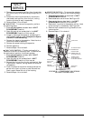
• The 52C,P unit may weigh up to 150 pounds. Use a
lifting device or ask for assistance if the unit must
be moved.
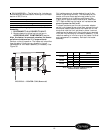
FIGURE 48 — INDOOR THERMOSTAT (IT)
CONTACTS, ALL 52CE, PE MODELS
LEGEND (Figures 48-50)
COMP —
Compressor
HTR —
Heater
IT —
Indoor Thermostat
OFT —
Outdoor Frost Thermostat
OL —
Overload
PLS —
Primary Limit Switch
SLS —
Secondary Limit Switch